


2-4. Interface
2-4. Interface
2-49
CLP-621 & CLP-631
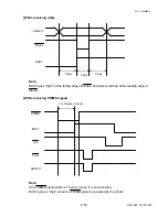
2-4-1. Serial Interface
(1) Specifications
System
Start/stop asynchronous full duplex communication
Signal level
RS-232C
Baud rate
2400, 4800, 9600, 19200, 38400, 57600, 115200 bps
Data length
7 bits, 8 bits
Stop bit
1 bit, 2 bits
Parity Odd,
even,
none
Connector
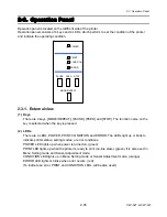
D-SUB JHBY-25S-1A3G 25PIN (JST)
(2) Signal line and pin assignment
Pin No. Signal Abbr.
Signal name
Function
1
FG
Frame ground
Protective grounding
2
TXD
Transmit Data
Signal line that transmits data from the printer to
the host
3
RXD
Receive data
Signal line that transmits data from the host to
the printer
4 RTS
Request
To
Send
Pulled up to +12V through 3.3 k
Ω
5 NC
------
Not
used
6
DSR
Data Set Ready
Signal line that is active when the host can
interface with the printer
7
SGND
Signal ground
Signal grounding line
8-17, 19 NC
------
Not used
14
VCC
+5V
(Factory use only )
20 DTR
Data
Terminal
Ready
Signal line that is active when the printer can
interface with the host
21-25 NC
------
Not
used
Summary of Contents for CLP-621
Page 1: ...Technical Manual CLP 621 CLP 631 Thermal Transfer Barcode Label Printer JM74961 00F 1 00E 0701...
Page 2: ...CLP 621 CLP 631 ii Copyright 2007 by CITIZEN SYSTEMS JAPAN CO LTD...
Page 4: ...CHAPTER 1 SPECIFICATIONS CLP 621 CLP 631...
Page 13: ...CHAPTER 2 OPERATING PRINCIPLES CLP 621 CLP 631...
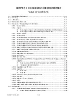
Page 73: ...CHAPTER 3 DISASSEMBLY AND MAINTENANCE CLP 621 CLP 631...
Page 126: ...CLP 621 CLP 631 CHAPTER 4 TROUBLESHOOTING...
Page 138: ...CLP 621 CLP 631 CHAPTER 5 PARTS LISTS...
Page 166: ...Chapter 5 Parts Lists CLP 621 CLP 631 5 29 DRAWING NO 7 Control Panel Unit Rev 0 4 3 2 1 5...
Page 177: ...Chapter 5 Parts Lists CLP 621 CLP 631 5 40 DRAWING NO 10 Accessories Rev 0 3 2 4 1...
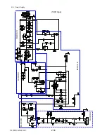
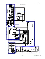
Page 179: ...CHAPTER 6 CIRCUIT DIAGRAMS CLP 621 CLP 631...
Page 208: ...APPENDICES CLP 621 CLP 631...
Page 212: ...B Mounting Diagrams AP 5 CLP 621 CLP 631 Main PCB Solder side...
Page 214: ...B Mounting Diagrams AP 7 CLP 621 CLP 631 B 3 Ribbon Main PCB Parts side Solder side...
Page 217: ......


