


3-5. Disassembly, Reassembly and Lubrication
CLP-621 & CLP-631
3-24
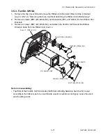
3-5-15. Sensor U Unit
1. Remove the Mechanism Unit. Refer to 3-5-13 “Mechanism Unit and Case L”.
2. Open the Head Block and detach the Sensor U Unit to set it free.
3. Remove 4 screws (PH, M2x4), and detach the Sensor U Unit.
Unit, Sensor U
C
: Approx. 2.5 cm (1")
(When the Head Block is fully raised.)
A
B
(Head Block)
C
PH, M2x4
Notes on reassembling:
• When assembling the Sensor U Unit, be sure that the protrusions “
A
” and “
B
” are securely
engaged with the respective holes as shown in the figure.
• When assembling the Sensor U Unit, be sure that the cable length “
C
” is approx. 2.5 cm (1”) with
the Head Block fully rose. If it is too long, the cable will be caught when the Head Block is
closed.
Summary of Contents for CLP-621
Page 1: ...Technical Manual CLP 621 CLP 631 Thermal Transfer Barcode Label Printer JM74961 00F 1 00E 0701...
Page 2: ...CLP 621 CLP 631 ii Copyright 2007 by CITIZEN SYSTEMS JAPAN CO LTD...
Page 4: ...CHAPTER 1 SPECIFICATIONS CLP 621 CLP 631...
Page 13: ...CHAPTER 2 OPERATING PRINCIPLES CLP 621 CLP 631...
Page 73: ...CHAPTER 3 DISASSEMBLY AND MAINTENANCE CLP 621 CLP 631...
Page 126: ...CLP 621 CLP 631 CHAPTER 4 TROUBLESHOOTING...
Page 138: ...CLP 621 CLP 631 CHAPTER 5 PARTS LISTS...
Page 166: ...Chapter 5 Parts Lists CLP 621 CLP 631 5 29 DRAWING NO 7 Control Panel Unit Rev 0 4 3 2 1 5...
Page 177: ...Chapter 5 Parts Lists CLP 621 CLP 631 5 40 DRAWING NO 10 Accessories Rev 0 3 2 4 1...
Page 179: ...CHAPTER 6 CIRCUIT DIAGRAMS CLP 621 CLP 631...
Page 208: ...APPENDICES CLP 621 CLP 631...
Page 212: ...B Mounting Diagrams AP 5 CLP 621 CLP 631 Main PCB Solder side...
Page 214: ...B Mounting Diagrams AP 7 CLP 621 CLP 631 B 3 Ribbon Main PCB Parts side Solder side...
Page 217: ......


