


4-2. Troubleshooting
CL
P-
621 & CLP-631
4-8
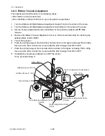
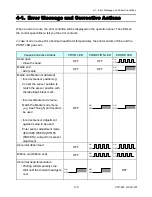
4-2-4. Ribbon-feed Problem
Symptoms
Checks
Remedies
Ribbon is fed in
reverse on the supply
side.
1. Is the ribbon type (inside wound ribbon
[ink in] or outside wound ribbon [ink
out]) matches the setting of the Ribbon
Winding Selection Switch?
2. Is the cable of the Fan/Dir. SW SA firmly
connected to the Ribbon Main PCB SA
(CN706)?
1. Set the Ribbon Winding Selection
Switch according to the ribbon
type to be used.
2. Connect it firmly.
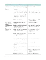
Ribbon is not fed at
all, or is not fed
correctly.
1. Is the ribbon correctly inserted into the
ribbon holders?
2. Is the ribbon path correct?
3. Is the cable connected between
CN8/CN21 on the Main PCB Unit and
CN701 on the Ribbon Main PCB SA
firmly?
4. Is the cable connected between CN702
on the Ribbon Main PCB SA and the
Ribbon Motor F SA firmly?
5. Is the cable connected between CN703
on the Ribbon Main PCB SA and the
Ribbon Motor R SA firmly?
6. Does the ribbon cooling fan work
correctly for cooling the ribbon motors?
If not, check if the cable of the Fan/Dir.
SW SA firmly connected to the Ribbon
Main PCB SA (CN706).
7. Do the ribbon sensors on the take-up
and supply sides work correctly?
See 4-2-5 “Sensor Problems”.
8. Do the ribbon drive gears work
correctly?
9. Does the Ribbon Motor F/R work
correctly?
10. Failure in the ribbon motor drive circuit.
11. Failure in the ribbon motor control
circuit.
1. Insert the ribbon correctly.
2. Install the ribbon correctly.
3. Connect it firmly.
4. Connect it firmly.
5. Connect it firmly.
6. Connect the cable firmly.
7. Replace the Tension Sensor SAs.
8. Replace the defective ribbon gear.
9. Replace the Ribbon Motor F SA or
Ribbon Motor R SA.
10. Replace the Ribbon Main PCB
SA.
11. Replace the Main PCB Unit.
Summary of Contents for CLP-621
Page 1: ...Technical Manual CLP 621 CLP 631 Thermal Transfer Barcode Label Printer JM74961 00F 1 00E 0701...
Page 2: ...CLP 621 CLP 631 ii Copyright 2007 by CITIZEN SYSTEMS JAPAN CO LTD...
Page 4: ...CHAPTER 1 SPECIFICATIONS CLP 621 CLP 631...
Page 13: ...CHAPTER 2 OPERATING PRINCIPLES CLP 621 CLP 631...
Page 73: ...CHAPTER 3 DISASSEMBLY AND MAINTENANCE CLP 621 CLP 631...
Page 126: ...CLP 621 CLP 631 CHAPTER 4 TROUBLESHOOTING...
Page 138: ...CLP 621 CLP 631 CHAPTER 5 PARTS LISTS...
Page 166: ...Chapter 5 Parts Lists CLP 621 CLP 631 5 29 DRAWING NO 7 Control Panel Unit Rev 0 4 3 2 1 5...
Page 177: ...Chapter 5 Parts Lists CLP 621 CLP 631 5 40 DRAWING NO 10 Accessories Rev 0 3 2 4 1...
Page 179: ...CHAPTER 6 CIRCUIT DIAGRAMS CLP 621 CLP 631...
Page 208: ...APPENDICES CLP 621 CLP 631...
Page 212: ...B Mounting Diagrams AP 5 CLP 621 CLP 631 Main PCB Solder side...
Page 214: ...B Mounting Diagrams AP 7 CLP 621 CLP 631 B 3 Ribbon Main PCB Parts side Solder side...
Page 217: ......


