


CHAPTER 2 OPERATING PRINCIPLES
TABLE OF CONTENTS
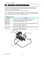
Locations and Functions of Motors, Sensors and Thermal Head.......................2-4
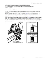
Print Head Up/Down Detection Mechanism .......................................................2-13
Head Balance Adjustment Mechanism...............................................................2-14
Head up sensor ............................................................................2-21
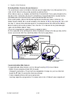
Transparent sensor and reflective sensor.....................................2-22
Tension sensor F/R.......................................................................2-24
Head temperature sensor .............................................................2-25
PF motor temperature sensor.......................................................2-26
Ribbon motor temperature sensor ................................................2-27
PF motor driver .............................................................................2-28
Ribbon motor driver ......................................................................2-29
Buzzer driver.................................................................................2-31
Fan driver......................................................................................2-32
CLP-621 & CLP-631
2-2
Summary of Contents for CLP-621
Page 1: ...Technical Manual CLP 621 CLP 631 Thermal Transfer Barcode Label Printer JM74961 00F 1 00E 0701...
Page 2: ...CLP 621 CLP 631 ii Copyright 2007 by CITIZEN SYSTEMS JAPAN CO LTD...
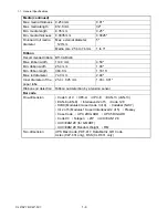
Page 4: ...CHAPTER 1 SPECIFICATIONS CLP 621 CLP 631...
Page 13: ...CHAPTER 2 OPERATING PRINCIPLES CLP 621 CLP 631...
Page 73: ...CHAPTER 3 DISASSEMBLY AND MAINTENANCE CLP 621 CLP 631...
Page 126: ...CLP 621 CLP 631 CHAPTER 4 TROUBLESHOOTING...
Page 138: ...CLP 621 CLP 631 CHAPTER 5 PARTS LISTS...
Page 166: ...Chapter 5 Parts Lists CLP 621 CLP 631 5 29 DRAWING NO 7 Control Panel Unit Rev 0 4 3 2 1 5...
Page 177: ...Chapter 5 Parts Lists CLP 621 CLP 631 5 40 DRAWING NO 10 Accessories Rev 0 3 2 4 1...
Page 179: ...CHAPTER 6 CIRCUIT DIAGRAMS CLP 621 CLP 631...
Page 208: ...APPENDICES CLP 621 CLP 631...
Page 212: ...B Mounting Diagrams AP 5 CLP 621 CLP 631 Main PCB Solder side...
Page 214: ...B Mounting Diagrams AP 7 CLP 621 CLP 631 B 3 Ribbon Main PCB Parts side Solder side...
Page 217: ......


