


2-1. Operation of Each Mechanism
2-11
CLP-621 & CLP-631
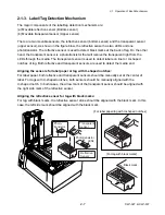
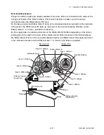
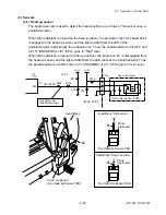
Reel Drive Mechanism:
Though the ribbon holders are directly installed in the reels, ribbon is connected to the reels via the
spring mechanism of the ribbon holders. This means that ribbon is taken up via the spring
mechanism when the Ribbon Motor F/R turns.
On the take-up side, the Ribbon Motor F turns in the clockwise direction viewing from the right side
of the printer, the Ribbon Gear 5F (take-up reel) turns in the counterclockwise direction via the
Ribbon Gears 1, 2, 3 and 4, and ribbon is taken up.
On the supply side, the rotational direction of the Ribbon Motor R differs depending on the ribbon
winding type to be used. In the case of the outside-wound ribbon as shown in the following figure,
the Ribbon Motor R turns in the counterclockwise direction, the Ribbon Gear 5R (supply reel) turns
in the clockwise direction via the Ribbon Gears 1, 2, 3 and 4, and ribbon is supplied.
Gear 5R, Ribbon
Gear 1, Ribbon
Gear 2, Ribbon
Gear 3, Ribbon
Gear 4, Ribbon
Ribbon Motor R
Ribbon Tension
Shaft R SA
Gear 5F, Ribbon
Gear 1, Ribbon
Gear 2, Ribbon
Gear 3, Ribbon
Gear 4, Ribbon
Ribbon Motor F
Ribbon Tension
Shaft F SA
Taku-up Side
Supply Side
Platen
Media
Ribbon
Thermal Head
Summary of Contents for CLP-621
Page 1: ...Technical Manual CLP 621 CLP 631 Thermal Transfer Barcode Label Printer JM74961 00F 1 00E 0701...
Page 2: ...CLP 621 CLP 631 ii Copyright 2007 by CITIZEN SYSTEMS JAPAN CO LTD...
Page 4: ...CHAPTER 1 SPECIFICATIONS CLP 621 CLP 631...
Page 13: ...CHAPTER 2 OPERATING PRINCIPLES CLP 621 CLP 631...
Page 73: ...CHAPTER 3 DISASSEMBLY AND MAINTENANCE CLP 621 CLP 631...
Page 126: ...CLP 621 CLP 631 CHAPTER 4 TROUBLESHOOTING...
Page 138: ...CLP 621 CLP 631 CHAPTER 5 PARTS LISTS...
Page 166: ...Chapter 5 Parts Lists CLP 621 CLP 631 5 29 DRAWING NO 7 Control Panel Unit Rev 0 4 3 2 1 5...
Page 177: ...Chapter 5 Parts Lists CLP 621 CLP 631 5 40 DRAWING NO 10 Accessories Rev 0 3 2 4 1...
Page 179: ...CHAPTER 6 CIRCUIT DIAGRAMS CLP 621 CLP 631...
Page 208: ...APPENDICES CLP 621 CLP 631...
Page 212: ...B Mounting Diagrams AP 5 CLP 621 CLP 631 Main PCB Solder side...
Page 214: ...B Mounting Diagrams AP 7 CLP 621 CLP 631 B 3 Ribbon Main PCB Parts side Solder side...
Page 217: ......


