


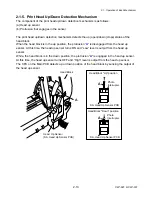


2-1. Operation of Each Mechanism
2-7
CLP-621 & CLP-631
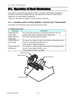
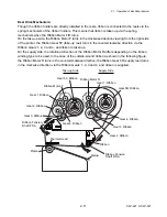
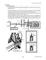
2-1-3. Label/Tag Detection Mechanism
The major components of the label/tag detection mechanism are:
(a) Movable reflective sensor (Bottom sensor)
(b) Movable transparent sensor (Upper sensor)
There are two movable sensors, the reflective sensor (bottom sensor) and the transparent sensor
(upper sensor). As shown in the figure blow, the reflective sensor has two LEDs and one
phototransistor. The reflective sensor is used to detect black marks at the back of tag. On the other
hand, the transparent sensor is a phototransistor that will receive the transparent light from the
LEDs through the media. The transparent sensor is used to detect labels on liner or U-shaped
notches of tag. Both reflective and transparent sensors are used to detect the media end.
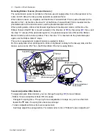
Aligning the sensors for label paper or tag with U-shaped notches:
For label paper, both reflective and transparent sensors should be manually set at the center of
label. For tags with U-shaped notches, both sensors should be manually aligned with the
U-shaped notch. In both cases, the arrow mark of the transparent sensor should be aligned with
the right side mark of the reflective sensor.
Aligning the reflective sensor for tag with black marks:
For tag with black marks, the reflective sensor alone should be aligned with the black mark. In this
case, the left side mark should be aligned with the black mark.
Phototransistor
LEDs
Photo-
transistor
Transparent
Sensor
Reflective
Sensor
[For label paper/tag with U-shaped notches]
Black mark
[For tag with black marks]
Summary of Contents for CLP-621
Page 1: ...Technical Manual CLP 621 CLP 631 Thermal Transfer Barcode Label Printer JM74961 00F 1 00E 0701...
Page 2: ...CLP 621 CLP 631 ii Copyright 2007 by CITIZEN SYSTEMS JAPAN CO LTD...
Page 4: ...CHAPTER 1 SPECIFICATIONS CLP 621 CLP 631...
Page 13: ...CHAPTER 2 OPERATING PRINCIPLES CLP 621 CLP 631...
Page 73: ...CHAPTER 3 DISASSEMBLY AND MAINTENANCE CLP 621 CLP 631...
Page 126: ...CLP 621 CLP 631 CHAPTER 4 TROUBLESHOOTING...
Page 138: ...CLP 621 CLP 631 CHAPTER 5 PARTS LISTS...
Page 166: ...Chapter 5 Parts Lists CLP 621 CLP 631 5 29 DRAWING NO 7 Control Panel Unit Rev 0 4 3 2 1 5...
Page 177: ...Chapter 5 Parts Lists CLP 621 CLP 631 5 40 DRAWING NO 10 Accessories Rev 0 3 2 4 1...
Page 179: ...CHAPTER 6 CIRCUIT DIAGRAMS CLP 621 CLP 631...
Page 208: ...APPENDICES CLP 621 CLP 631...
Page 212: ...B Mounting Diagrams AP 5 CLP 621 CLP 631 Main PCB Solder side...
Page 214: ...B Mounting Diagrams AP 7 CLP 621 CLP 631 B 3 Ribbon Main PCB Parts side Solder side...
Page 217: ......


