


2-2. Operation of Control Parts
trol Parts
CLP-621 & CLP-631
2-28
CLP-621 & CLP-631
2-28
(4) Drivers
(4) Drivers
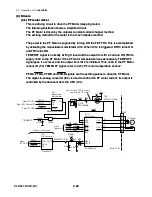
(4-1) PF motor driver
(4-1) PF motor driver
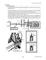
This is a driving circuit to drive the PF Motor (stepping motor).
This is a driving circuit to drive the PF Motor (stepping motor).
The following illustration shows a simplified circuit.
The following illustration shows a simplified circuit.
The PF Motor is driven by the unipolar constant current chopper method.
The PF Motor is driven by the unipolar constant current chopper method.
The exciting method for the motor is the 1st-2nd phase method.
The exciting method for the motor is the 1st-2nd phase method.
The power to the PF Motor is supplied by turning ON the FET TR3. This is accomplished
by activating the monostable multivibrator IC12. When IC12 is triggered, DTR3 turns ON
and TR3 turns ON.
The power to the PF Motor is supplied by turning ON the FET TR3. This is accomplished
by activating the monostable multivibrator IC12. When IC12 is triggered, DTR3 turns ON
and TR3 turns ON.
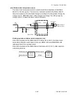
TEMPOFF signal is normally at “High” level and the output from IC12 can turn ON TR3 to
24V to the PF Motor. If the PF motor temperature rises excessively, TEMPOFF
signal goes “Low” level, and the output from IC12 is inhibited. Thus,+24V to the PF Motor
is shut off. (For TEMPOFF signal, refer to (3-5) “PF motor temperature sensor”.
PFMA, PFMA, PFMB and PFMB signals are the exciting pulses to drive the PF Motor.
PFMA, PFMA, PFMB and PFMB signals are the exciting pulses to drive the PF Motor.
The digital-to-analog converter (IC4) is used to control the PF motor current. Its output is
controlled by the data sent from the CPU (IC1).
The digital-to-analog converter (IC4) is used to control the PF motor current. Its output is
controlled by the data sent from the CPU (IC1).
12
6
7
17
5
16
VSA
VSB
INA
INA
INB
INB
IC13
Motor Driver
1
2
3
4
5
CN5
OUT A
OUT A
OUT B
OUT B
M
PF Motor
1
8
11
18
IC12
Monostable
Multivibrator
1CLR1
1A1
1
2
1B
3
1Q
13
DTR3
DTC143EUA
P182
TR3
XP132A11A1SR
PFCLK
From IC1 CPU
PFON
From IC11 Custom IC
GRESET
From IC1 CPU
SN74LV123APWR
From
Custom IC
14
REFA
REFB
R93
C66
R94
R92
IC4
D/A Converter
CS
DIN
1
2
SCLK
3
OUTA
4
DACCLK
DACCS
DACIN
From
IC1 CPU
TLV5625ID
P197
T12
PFCU
PFMOTCU
R89
[Main PCB]
Low: Turns on TR3 to supply
power to the PF motor.
Motor current control
PFMA
PFMA
PFMB
PFMB
3
P191
P188
P190
P189
R168
TEMPOFF
C105
1
4
2
IC22A
SLA7024M
+24V
R86
R88
P187
Summary of Contents for CLP-621
Page 1: ...Technical Manual CLP 621 CLP 631 Thermal Transfer Barcode Label Printer JM74961 00F 1 00E 0701...
Page 2: ...CLP 621 CLP 631 ii Copyright 2007 by CITIZEN SYSTEMS JAPAN CO LTD...
Page 4: ...CHAPTER 1 SPECIFICATIONS CLP 621 CLP 631...
Page 13: ...CHAPTER 2 OPERATING PRINCIPLES CLP 621 CLP 631...
Page 73: ...CHAPTER 3 DISASSEMBLY AND MAINTENANCE CLP 621 CLP 631...
Page 126: ...CLP 621 CLP 631 CHAPTER 4 TROUBLESHOOTING...
Page 138: ...CLP 621 CLP 631 CHAPTER 5 PARTS LISTS...
Page 166: ...Chapter 5 Parts Lists CLP 621 CLP 631 5 29 DRAWING NO 7 Control Panel Unit Rev 0 4 3 2 1 5...
Page 177: ...Chapter 5 Parts Lists CLP 621 CLP 631 5 40 DRAWING NO 10 Accessories Rev 0 3 2 4 1...
Page 179: ...CHAPTER 6 CIRCUIT DIAGRAMS CLP 621 CLP 631...
Page 208: ...APPENDICES CLP 621 CLP 631...
Page 212: ...B Mounting Diagrams AP 5 CLP 621 CLP 631 Main PCB Solder side...
Page 214: ...B Mounting Diagrams AP 7 CLP 621 CLP 631 B 3 Ribbon Main PCB Parts side Solder side...
Page 217: ......


