


1-3. Printing Position Accuracy
1-3. Printing Position Accuracy
CLP-621 & CLP-631
1-8
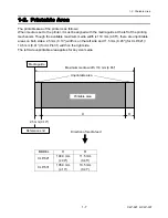
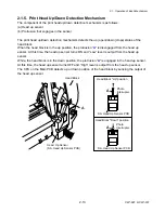
By default, the printing start position is 2.5 mm (0.10") from the left end of the media and 1 mm
(0.04") backward the leading edge of the label, U-shaped notch, or black mark.
2.5 mm (0.10") is the necessary value to avoid printing in the unprintable area as mentioned in 1-2
"Printable Area".
The printing start position will deviate from the ideal position as follows:
1
±
2 mm*
2
(0.04
±
0.08")
Reference edge
(Paper guide)
Printable area
Direction of media feed
Ideal printing start position
Actual printing start position*
1
2.5
±
1 mm*
3
(0.10
±
0.04")
100
±
2 mm*
4
(39.4
±
0.08")
Maximum media width: 118 mm (4.65")
Unprint
able area
2.5 mm
(0.10")
*1: Actual printing start position. May deviates from the ideal one in the indicated range.
*2: Deviation of vertical positioning when printing position is set to 0.
*3: Deviation of horizontal positioning when printing position is set to 0.
*4: Deviation of vertical printing position when 100 mm is specified from the printing start
position.
1 mm (0.04")
Unprint
able area
Summary of Contents for CLP-621
Page 1: ...Technical Manual CLP 621 CLP 631 Thermal Transfer Barcode Label Printer JM74961 00F 1 00E 0701...
Page 2: ...CLP 621 CLP 631 ii Copyright 2007 by CITIZEN SYSTEMS JAPAN CO LTD...
Page 4: ...CHAPTER 1 SPECIFICATIONS CLP 621 CLP 631...
Page 13: ...CHAPTER 2 OPERATING PRINCIPLES CLP 621 CLP 631...
Page 73: ...CHAPTER 3 DISASSEMBLY AND MAINTENANCE CLP 621 CLP 631...
Page 126: ...CLP 621 CLP 631 CHAPTER 4 TROUBLESHOOTING...
Page 138: ...CLP 621 CLP 631 CHAPTER 5 PARTS LISTS...
Page 166: ...Chapter 5 Parts Lists CLP 621 CLP 631 5 29 DRAWING NO 7 Control Panel Unit Rev 0 4 3 2 1 5...
Page 177: ...Chapter 5 Parts Lists CLP 621 CLP 631 5 40 DRAWING NO 10 Accessories Rev 0 3 2 4 1...
Page 179: ...CHAPTER 6 CIRCUIT DIAGRAMS CLP 621 CLP 631...
Page 208: ...APPENDICES CLP 621 CLP 631...
Page 212: ...B Mounting Diagrams AP 5 CLP 621 CLP 631 Main PCB Solder side...
Page 214: ...B Mounting Diagrams AP 7 CLP 621 CLP 631 B 3 Ribbon Main PCB Parts side Solder side...
Page 217: ......


