


3-6. Adjustments
3-53
CLP-621 & CLP-631
3-53
CLP-621 & CLP-631
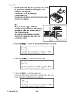
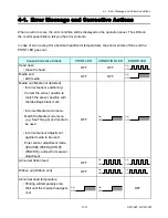
9. While inserting a small screwdriver into the tension adjust screw through the hole, adjust the
screw so that the LED changes from OFF to ON when the following tension is applied to the
knob:
9. While inserting a small screwdriver into the tension adjust screw through the hole, adjust the
screw so that the LED changes from OFF to ON when the following tension is applied to the
knob:
Front (take-up) side: 350 to 380g
Rear (supply) side: 350 to 400g
Note:
After adjustment, apply Threebond 1401B to the screw to fix it.
Front (take-up) side: 350 to 380g
Rear (supply) side: 350 to 400g
Note:
After adjustment, apply Threebond 1401B to the screw to fix it.
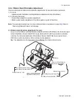
Front Tension Adjustment Screw
Apply Threebond 1401B.
Back Tension Adjustment Screw
Apply Threebond 1401B.
10. After completion of adjustment, turn OFF the printer.
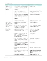
3-6-4. Maintenance Information - Head Adjust Shim
Depending on the printer, the Head Adjust Shim may be added at the factory to obtain correct
adjustable range of the Media Thickness Adjustment Dial. At the factory, the following adjustment
is performed:
Note:
This adjustment is not required for service work normally.
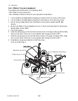
1. A line is printed with the Media Thickness
Adjustment Dial set to “0”.
2. If the line is faint, the Head Adjust Shim(s)
is(are) added.
[OK]
[NG]
SA, Head Adjust
(Media Thickness
Adjustment Dial)
Shim, Head Adjust
Summary of Contents for CLP-621
Page 1: ...Technical Manual CLP 621 CLP 631 Thermal Transfer Barcode Label Printer JM74961 00F 1 00E 0701...
Page 2: ...CLP 621 CLP 631 ii Copyright 2007 by CITIZEN SYSTEMS JAPAN CO LTD...
Page 4: ...CHAPTER 1 SPECIFICATIONS CLP 621 CLP 631...
Page 13: ...CHAPTER 2 OPERATING PRINCIPLES CLP 621 CLP 631...
Page 73: ...CHAPTER 3 DISASSEMBLY AND MAINTENANCE CLP 621 CLP 631...
Page 126: ...CLP 621 CLP 631 CHAPTER 4 TROUBLESHOOTING...
Page 138: ...CLP 621 CLP 631 CHAPTER 5 PARTS LISTS...
Page 166: ...Chapter 5 Parts Lists CLP 621 CLP 631 5 29 DRAWING NO 7 Control Panel Unit Rev 0 4 3 2 1 5...
Page 177: ...Chapter 5 Parts Lists CLP 621 CLP 631 5 40 DRAWING NO 10 Accessories Rev 0 3 2 4 1...
Page 179: ...CHAPTER 6 CIRCUIT DIAGRAMS CLP 621 CLP 631...
Page 208: ...APPENDICES CLP 621 CLP 631...
Page 212: ...B Mounting Diagrams AP 5 CLP 621 CLP 631 Main PCB Solder side...
Page 214: ...B Mounting Diagrams AP 7 CLP 621 CLP 631 B 3 Ribbon Main PCB Parts side Solder side...
Page 217: ......


