


3-5. Disassembly, Reassembly and Lubrication
3-31
CLP-621 & CLP-631
Notes on reassembling:
When assembling the Head Unit, follow the next steps:
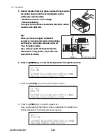
1. Set the blue dials as follows:
Media width adjustment dial:
Location “0” (for easier assembling)
Media thickness adjustment dial: Location “9”
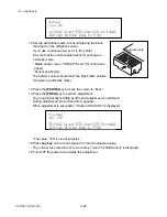
2. Insert the end “
A
” of the Head Unit into the Head Adjust SA (
c
) and align its position as
shown in the figure (
d
). (In this position, the screw “
B
” of the Head Unit can be correctly
inserted into the slit “
C
” of the frame. If the screw “
B
” is not inserted into the slit “
C
”, the
Head Unit cannot be correctly seated.)
3. While lightly pressing down the Head Unit (
e
), move it toward the rear to hook its rear
sides on the claws “
D
” of the frame (
f
).
4. Set the media width adjustment dial to the location “5” to give tension to the Head Unit.
(Unit, Head)
Cam, Head Balance
(Media Width Adjustment Dial)
(Media Thickness Adjustment Dial)
Claw
D
1
3
3
4
4
"0"
"9" to "5"
Screw
B
Slit
C
Align like this.
2
End
A
1
SA, Head Adjust
Summary of Contents for CLP-621
Page 1: ...Technical Manual CLP 621 CLP 631 Thermal Transfer Barcode Label Printer JM74961 00F 1 00E 0701...
Page 2: ...CLP 621 CLP 631 ii Copyright 2007 by CITIZEN SYSTEMS JAPAN CO LTD...
Page 4: ...CHAPTER 1 SPECIFICATIONS CLP 621 CLP 631...
Page 13: ...CHAPTER 2 OPERATING PRINCIPLES CLP 621 CLP 631...
Page 73: ...CHAPTER 3 DISASSEMBLY AND MAINTENANCE CLP 621 CLP 631...
Page 126: ...CLP 621 CLP 631 CHAPTER 4 TROUBLESHOOTING...
Page 138: ...CLP 621 CLP 631 CHAPTER 5 PARTS LISTS...
Page 166: ...Chapter 5 Parts Lists CLP 621 CLP 631 5 29 DRAWING NO 7 Control Panel Unit Rev 0 4 3 2 1 5...
Page 177: ...Chapter 5 Parts Lists CLP 621 CLP 631 5 40 DRAWING NO 10 Accessories Rev 0 3 2 4 1...
Page 179: ...CHAPTER 6 CIRCUIT DIAGRAMS CLP 621 CLP 631...
Page 208: ...APPENDICES CLP 621 CLP 631...
Page 212: ...B Mounting Diagrams AP 5 CLP 621 CLP 631 Main PCB Solder side...
Page 214: ...B Mounting Diagrams AP 7 CLP 621 CLP 631 B 3 Ribbon Main PCB Parts side Solder side...
Page 217: ......


