


3-5. Disassembly, Reassembly and Lubrication
CLP-621 & CLP-631
3-28
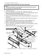
3-5-17. Head Block and PF Unit
1. Remove the Mechanism Unit. Refer to 3-5-13 “Mechanism Unit and Case L”.
2. Remove 1 screw (BH (N), M3x3) to detach the Cable Guide Plate (
1
) from the Head Block.
3. Remove 1 screw (PH, M3x6) (
2
) to detach the earth lug from the frame.
4. Open the Head Block and disengage the Head Up Spring (
3
) and the Head Up Spring 2 (
4
)
from the Mechanism Unit.
Note:
Hold the Head Block as it can fall when the springs are removed.
5. Remove 1 screw (PH (SW+PW), M4x16) and the Head Holder Shaft (
5
).
6. Disengage 1 E-ring and detach the Head Block (
6
) from the PF Unit Block.
7. Remove 1 screw (BH (N), M3x6) and remove the Motor Cover Bracket (
7
) from the PF Unit
Block.
8. Remove 1 screw (BH (N), M3x6) and remove the Head Up Spring 2 Hook (
8
) from the PF Unit
Block.
Lower side Wire Tie
(Flat side)
5
Shaft, Head Holder
(
6
Head Block)
3
Spring, Head Up
4
Spring2, Head Up
Unit, PF
PH (SW+PW), M4x16
2
PH, M3x6
E-Ring, 4
7
Bracket, Motor
Cover
8
Hook, Head Up Spring 2
BH (N), M3x6
Open ends of
the spring
BH (N), M3x3
FLOIL G-311S
FLOIL G-311S
FLOIL G-311S
1
Plate, Cable Guide
BH (N), M3x6
FLOIL G-311S
A
B
C
D
Notes on reassembling:
• When assembling, apply G-311S to the following places shown by the mark.
A
: Hole (front left). Circumference surface of the hole (on both sides) and inside the hole
B
: Hole and protrusion (rear left). Circumference surface of the hole (on both sides) and along
the protrusion surface.
C
: Along the contacting surface (rear left).
D
: 3 surfaces on the Head Holder Shaft.
• When assembling the Head Holder Shaft, be sure that its assembling direction is correct.
Summary of Contents for CLP-621
Page 1: ...Technical Manual CLP 621 CLP 631 Thermal Transfer Barcode Label Printer JM74961 00F 1 00E 0701...
Page 2: ...CLP 621 CLP 631 ii Copyright 2007 by CITIZEN SYSTEMS JAPAN CO LTD...
Page 4: ...CHAPTER 1 SPECIFICATIONS CLP 621 CLP 631...
Page 13: ...CHAPTER 2 OPERATING PRINCIPLES CLP 621 CLP 631...
Page 73: ...CHAPTER 3 DISASSEMBLY AND MAINTENANCE CLP 621 CLP 631...
Page 126: ...CLP 621 CLP 631 CHAPTER 4 TROUBLESHOOTING...
Page 138: ...CLP 621 CLP 631 CHAPTER 5 PARTS LISTS...
Page 166: ...Chapter 5 Parts Lists CLP 621 CLP 631 5 29 DRAWING NO 7 Control Panel Unit Rev 0 4 3 2 1 5...
Page 177: ...Chapter 5 Parts Lists CLP 621 CLP 631 5 40 DRAWING NO 10 Accessories Rev 0 3 2 4 1...
Page 179: ...CHAPTER 6 CIRCUIT DIAGRAMS CLP 621 CLP 631...
Page 208: ...APPENDICES CLP 621 CLP 631...
Page 212: ...B Mounting Diagrams AP 5 CLP 621 CLP 631 Main PCB Solder side...
Page 214: ...B Mounting Diagrams AP 7 CLP 621 CLP 631 B 3 Ribbon Main PCB Parts side Solder side...
Page 217: ......


