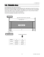


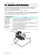


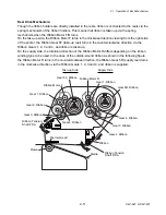


2-1. Operation of Each Mechanism
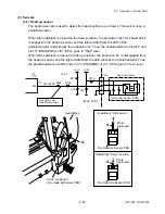
Detecting Ribbon Tension (Tension Sensors):
The same tension sensor is installed on the take-up and supply sides. Since the operation is the
same on both sides, the take-up side operation is explained here:
When ribbon is taken up, it tightens and the Ribbon Tension Shaft F SA is pushed inward (in the
direction of “
A
”). At this time, the claw “
C
” of the Ribbon Tension Shaft F SA is inserted into the
photointerrupter of the tension sensor, and the photointerrupter turns OFF.
When printing starts, ribbon is fed forward together with media and it slacks. At this time, the
Ribbon Tension Shaft F SA is moved outward (in the direction of “
B
”) by the spring (“
D
”) force, and
the claw “C” comes off the photointerrupter. So, the photointerrupter turns ON and the Ribbon
Motor F starts to turn to take up ribbon. Then, the claw “C” is inserted into the photointerrupter
again, and the Ribbon Motor F stops.
This cycle is repeated and constant tension is applied to ribbon.
On the supply side, when printing starts, ribbon is tightened contrary to the take-up side, and the
tension sensor turns ON. Then, the Ribbon Motor R turns to supply ribbon.
Tension Adjustment
Knob (Front)
Tension Sensor SA
(Photointerrupter)
Supporting Point
Ribbon Tension
Shaft F SA
Ribbon
D
Ribbon
A
B
C
Springs
Tension Adjustment
Knob (Rear)
[Right side view]
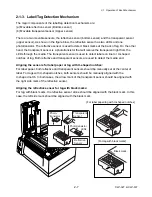
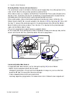
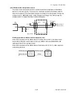
Tension Adjustment Mechanism:
To apply adequate ribbon tension, you can change the spring (“
D
”) force as follows:
- Ribbon Tension Adjustment Knob F/R (for users)
Changes the spring force. The spring force is adjustable in 3 steps. As you move the knob
toward the
T
mark, the spring force becomes stronger .
- Tension Adjustment Screw (for service personnel)
Can finely adjust the spring position. For details, refer to 3-6-3 “Ribbon Tension Adjustment”.
CLP-621 & CLP-631
2-12
Summary of Contents for CLP-621
Page 1: ...Technical Manual CLP 621 CLP 631 Thermal Transfer Barcode Label Printer JM74961 00F 1 00E 0701...
Page 2: ...CLP 621 CLP 631 ii Copyright 2007 by CITIZEN SYSTEMS JAPAN CO LTD...
Page 4: ...CHAPTER 1 SPECIFICATIONS CLP 621 CLP 631...
Page 13: ...CHAPTER 2 OPERATING PRINCIPLES CLP 621 CLP 631...
Page 73: ...CHAPTER 3 DISASSEMBLY AND MAINTENANCE CLP 621 CLP 631...
Page 126: ...CLP 621 CLP 631 CHAPTER 4 TROUBLESHOOTING...
Page 138: ...CLP 621 CLP 631 CHAPTER 5 PARTS LISTS...
Page 166: ...Chapter 5 Parts Lists CLP 621 CLP 631 5 29 DRAWING NO 7 Control Panel Unit Rev 0 4 3 2 1 5...
Page 177: ...Chapter 5 Parts Lists CLP 621 CLP 631 5 40 DRAWING NO 10 Accessories Rev 0 3 2 4 1...
Page 179: ...CHAPTER 6 CIRCUIT DIAGRAMS CLP 621 CLP 631...
Page 208: ...APPENDICES CLP 621 CLP 631...
Page 212: ...B Mounting Diagrams AP 5 CLP 621 CLP 631 Main PCB Solder side...
Page 214: ...B Mounting Diagrams AP 7 CLP 621 CLP 631 B 3 Ribbon Main PCB Parts side Solder side...
Page 217: ......


