


3-5. Disassembly, Reassembly and Lubrication
3-27
CLP-621 & CLP-631
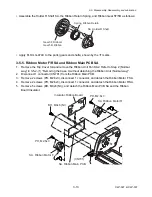
• When assembling the Transparent Sensor Cable SA, run it as shown below. Be sure that it
passes 2 slits (“
A
” and “
B
”), and the free end is hooked on the protrusion and passes the slit
“
C
”.
SA, Transparent Sensor Cable
Slit A
Cap, Sensor Cable U
Protrusion
Slit B
Slit C
[Bottom View]
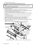
• When assembling the Sensor Cable U Cap, be sure that it is securely seated as shown
below: The notched corner should be engaged with the chassis securely.
SA, Transparent
Sensor Cable
Cap, Sensor Cable U
Tape, Sensor Cable U
D
Fixing the spring
(Shorter slit)
Spring, Sensor Frame
Cap, Sensor Frame L
Cover, Head Wire
Sensor U Hoder body
Cable for pulling
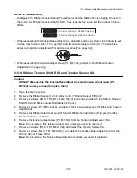
• When assembling the Sensor U Holder body
on the Head Wire Cover, engage the Sensor
Frame Spring as follows.
1) Insert the long end of the spring into the
shorter slit of the Head Wire Cover.
2) Hook a cable wire or similar on the short
end of the spring, and pull it to lower the
short end of the spring.
3) While pulling the cable wire, assemble
the Sensor U Holder body on the Head
Wire Cover, and then hook the short end
of the spring on the part “D” of the
Sensor Frame L Cap.
Summary of Contents for CLP-621
Page 1: ...Technical Manual CLP 621 CLP 631 Thermal Transfer Barcode Label Printer JM74961 00F 1 00E 0701...
Page 2: ...CLP 621 CLP 631 ii Copyright 2007 by CITIZEN SYSTEMS JAPAN CO LTD...
Page 4: ...CHAPTER 1 SPECIFICATIONS CLP 621 CLP 631...
Page 13: ...CHAPTER 2 OPERATING PRINCIPLES CLP 621 CLP 631...
Page 73: ...CHAPTER 3 DISASSEMBLY AND MAINTENANCE CLP 621 CLP 631...
Page 126: ...CLP 621 CLP 631 CHAPTER 4 TROUBLESHOOTING...
Page 138: ...CLP 621 CLP 631 CHAPTER 5 PARTS LISTS...
Page 166: ...Chapter 5 Parts Lists CLP 621 CLP 631 5 29 DRAWING NO 7 Control Panel Unit Rev 0 4 3 2 1 5...
Page 177: ...Chapter 5 Parts Lists CLP 621 CLP 631 5 40 DRAWING NO 10 Accessories Rev 0 3 2 4 1...
Page 179: ...CHAPTER 6 CIRCUIT DIAGRAMS CLP 621 CLP 631...
Page 208: ...APPENDICES CLP 621 CLP 631...
Page 212: ...B Mounting Diagrams AP 5 CLP 621 CLP 631 Main PCB Solder side...
Page 214: ...B Mounting Diagrams AP 7 CLP 621 CLP 631 B 3 Ribbon Main PCB Parts side Solder side...
Page 217: ......


