


3-6. Adjustments
3-45
CLP-621 & CLP-631
3-6-2. Ribbon Slant Elimination Adjustment
There are two kinds of ribbon slant elimination adjustments: for user and service personnel.
1) For User
• Adjustment with the Ribbon Left-Right Balance Adjustment Knobs (Front/Rear)
2) For Service Personnel
• Tension Base Adjust Cam position adjustment:
• Ribbon guide position adjustment (The ribbon guide is a part of Head SA.)
Note
: The general procedure how to remove ribbon wrinkles is explained on page
3-50
. Refer to
“Removing Ribbon Wrinkles” on that page.
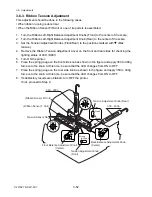
(1) Ribbon slant elimination adjustment (For user)
As you turn the Ribbon Left-Right Balance Adjustment Knobs (Front/Rear), the knob side (right
side) of the Ribbon Tension Shaft F SA moves back and forth with the eccentric mechanism,
and also, the knob side (right side) of the Ribbon Tension Shaft R SA moves up and down.
With this eccentric mechanism, ribbon running can be adjusted.
Tip:
The adjustment on the front side is more effective than that on the rear side.
Ribbon
SA, Ribbon Tension Shaft F
SA, Ribbon Tension Shaft R
Ribbon Sensor R Unit
Ribbon Sensor F Unit
Ribbon Left-Right Balance
Adjustment Knob (Front)
Ribbon Left-Right Balance
Adjustment Knob (Rear)
SA, Ribbon Sensor Frame F
SA, Ribbon Sensor Frame R
Summary of Contents for CLP-621
Page 1: ...Technical Manual CLP 621 CLP 631 Thermal Transfer Barcode Label Printer JM74961 00F 1 00E 0701...
Page 2: ...CLP 621 CLP 631 ii Copyright 2007 by CITIZEN SYSTEMS JAPAN CO LTD...
Page 4: ...CHAPTER 1 SPECIFICATIONS CLP 621 CLP 631...
Page 13: ...CHAPTER 2 OPERATING PRINCIPLES CLP 621 CLP 631...
Page 73: ...CHAPTER 3 DISASSEMBLY AND MAINTENANCE CLP 621 CLP 631...
Page 126: ...CLP 621 CLP 631 CHAPTER 4 TROUBLESHOOTING...
Page 138: ...CLP 621 CLP 631 CHAPTER 5 PARTS LISTS...
Page 166: ...Chapter 5 Parts Lists CLP 621 CLP 631 5 29 DRAWING NO 7 Control Panel Unit Rev 0 4 3 2 1 5...
Page 177: ...Chapter 5 Parts Lists CLP 621 CLP 631 5 40 DRAWING NO 10 Accessories Rev 0 3 2 4 1...
Page 179: ...CHAPTER 6 CIRCUIT DIAGRAMS CLP 621 CLP 631...
Page 208: ...APPENDICES CLP 621 CLP 631...
Page 212: ...B Mounting Diagrams AP 5 CLP 621 CLP 631 Main PCB Solder side...
Page 214: ...B Mounting Diagrams AP 7 CLP 621 CLP 631 B 3 Ribbon Main PCB Parts side Solder side...
Page 217: ......


