


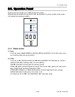


2-3. Operation Panel
CLP-621 & CLP-631
2-38
2-38
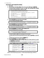
(2) Test mode
(2) Test mode
The following test modes are available.
The following test modes are available.
Operation
Description
Remarks
[FEED] + [POWER]
Enters self print mode
See (2-1).
[STOP] + [POWER]
Enters hex dump mode
See (2-2).
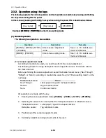
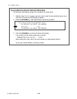
(2-1) Self print mode
You can check the printing quality by printing the self print pattern.
For label (prints 2 labels):
Media feed direction
<Example of CLP-621>
[Print pattern in self print mode]
1. While pressing and holding the
[FEED]
key, turn
on the power.
2. When the PRINT LED blinks slowly (later, it will
blink rapidly), release the
[FEED]
key.
The printer enters self print mode. The label is
fed, self test printing is made for two labels, and
then printing stops.
3. To repeat printing, press the
[FEED]
key again.
To exit self print mode, turn off the power.
For continuous media:
1. While pressing and holding the
[FEED]
key, turn
on the power.
2. The PRINT LED will blink slowly. When it
changes to rapid blink, release the
[FEED]
key.
The printer enters self print mode and self test
printing is made.
3. To repeat printing, press the
[FEED]
key again.
To exit self print mode, turn off the power.
Summary of Contents for CLP-621
Page 1: ...Technical Manual CLP 621 CLP 631 Thermal Transfer Barcode Label Printer JM74961 00F 1 00E 0701...
Page 2: ...CLP 621 CLP 631 ii Copyright 2007 by CITIZEN SYSTEMS JAPAN CO LTD...
Page 4: ...CHAPTER 1 SPECIFICATIONS CLP 621 CLP 631...
Page 13: ...CHAPTER 2 OPERATING PRINCIPLES CLP 621 CLP 631...
Page 73: ...CHAPTER 3 DISASSEMBLY AND MAINTENANCE CLP 621 CLP 631...
Page 126: ...CLP 621 CLP 631 CHAPTER 4 TROUBLESHOOTING...
Page 138: ...CLP 621 CLP 631 CHAPTER 5 PARTS LISTS...
Page 166: ...Chapter 5 Parts Lists CLP 621 CLP 631 5 29 DRAWING NO 7 Control Panel Unit Rev 0 4 3 2 1 5...
Page 177: ...Chapter 5 Parts Lists CLP 621 CLP 631 5 40 DRAWING NO 10 Accessories Rev 0 3 2 4 1...
Page 179: ...CHAPTER 6 CIRCUIT DIAGRAMS CLP 621 CLP 631...
Page 208: ...APPENDICES CLP 621 CLP 631...
Page 212: ...B Mounting Diagrams AP 5 CLP 621 CLP 631 Main PCB Solder side...
Page 214: ...B Mounting Diagrams AP 7 CLP 621 CLP 631 B 3 Ribbon Main PCB Parts side Solder side...
Page 217: ......


