ENGINE 6-2
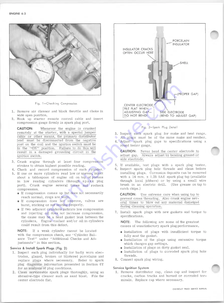
INSULATOR CR A CK S
OFTEN O CCU R HERE
CENTER ELECTRODE
FILE FLAT W HEN
A D JU STIN G G A P -
DO NOT BEND!
PORCELAIN
INSULATOR
SHELL
(PROPER GAP)
SIDE ELECTRODE
(BEND TO ADJUST GAP)
Fig. 1—Checking Compression
1. Remove air cleaner and block throttle and choke in
wide open position.
2. Hook up starter remote control cable and insert
compression gauge firm ly in spark plug port.
CA U TIO N :
Whenever the engine is cranked
remotely at the starter, with a special jumper
cable or other means, the primary distributor
lead must be disconnected from the negative
post on the coil and the ignition switch must be
in the "O N ” position.
Failure to do this will
result in a damaged grounding circuit in the
ignition switch.
3. Crank engine through at least four compression
strokes to obtain highest possible reading.
4. Check and record compression of each cylinder.
5. If one or more cylinders read low or uneven, inject
about a tablespoon of engine oil on top of pistons
in low reading cylinders (through s p a r k plug
port). Crank engine several times and recheck
compression.
• If compression comes up but does not necessarily
reach normal, rings are worn.
• If compression does not improve, valves are
burnt, sticking or not seating properly.
• If two adjacent cylinders indicate low compression
and injecting oil does not increase compression,
the cause may be a head gasket leak between the
cylinders.
Engine coolant and/or oil in cylinders
could result from this defect.
NOTE:
If a weak cylinder cannot be located
with the compression check, see "Cylinder Bal
ance Test” under "Additional Checks and Ad
justments” in this section.
Service & Install Spark Plugs (Fig. 2)
1. Inspect each plug individually for badly worn elec
trodes, glazed, broken or blistered porcelains and
replace plugs where necessary.
Refer to spark
plug diagnosis information presented in Section 6Y
for an analysis of plug conditions.
2. Clean serviceable spark plugs thoroughly, using an
abrasive-type cleaner such as sand blast.
File the
center electrode flat.
F ig . 2—Spark Plug Detail
3. Inspect each spark plug for make and heat range.
All plugs must be of the same make and number.
4. Adjust spark plug gaps to specifications using a
round feeler gauge.
CA U TIO N :
Never bend the center electrode to
adjust gap. Always adjust by bending ground or
side electrode.
5. If available, test plugs with a spark plug tester.
6. Inspect spark plug hole threads and clean before
installing plugs. Corrosion deposits can be removed
with a 14 mm. x 1.25 SAE sparkplug tap (available
through local jobbers) or by using a small wire
brush in an electric drill.
(Use grease on tap to
catch chips.)
C A U TIO N :
Use extreme care when using tap to
prevent cross threading. Also crank engine sev
eral times to blow out any material dislodged
during cleaning operation.
7. Install spark plugs with new gaskets and torque to
specifications.
N OTE:
The following are some of the greatest
causes of unsatisfactory spark plug performance.
• Installation of plugs with insufficient torque to
fully seat the gasket.
• Installation of the plugs using excessive torque
which changes gap settings.
• Installation of plugs on dirty gasket seal.
• Installation of plugs to corroded spark plug hole
threads.
8. Connect spark plug wiring.
Service Ignition System
1. Remove distributor cap, clean cap and inspect for
cracks, carbon tracks and burned or corroded ter
minals. Replace cap where necessary.
CHEVROLET TRUCK SERVICE MANUAL
Summary of Contents for 10 Series 1968
Page 1: ...ST 1 3 3 SB...
Page 3: ...w w...
Page 52: ...HEATER AND AIR CONDITIONING 1A 21 Fig 32 Charging Schematic CHEVROLET TRUCK SERVICE MANUAL...
Page 67: ......
Page 128: ...BODY IB 61 Fig 135 A uxiliary Seat CHEVROLET TRUCK SERVICE MANUAL...
Page 132: ...Fig 4 1 0 3 0 Series Truck Frame...
Page 133: ...Fig 5 4 0 6 0 Single A xle Truck Frame E x c Tilt Cab...
Page 135: ...Fig 7 4 0 6 0 Series Tilt Cab Truck Frames...
Page 139: ...w...
Page 169: ...fit w...
Page 233: ...I...
Page 248: ...BRAKES 5 15 TD 50 60 Fig 26 Parking Brake Cables T Models CHEVROLET TRUCK SERVICE MANUAL...
Page 347: ......
Page 389: ......
Page 393: ......
Page 411: ...ENGINE FUEL 6M 18 Fig 18A V 8 Typical CHEVROLET TRUCK SERVICE MANUAL...
Page 525: ......
Page 551: ......
Page 583: ...CHASSIS SHEET METAL 11 12 Fig 20 Designation and Name Plate CHEVROLET TRUCK SERVICE MANUAL...
Page 587: ...ELECTRICAL BODY AND CHASSIS 12 2 Fig 1 Fuse Panel CHEVROLET TRUCK SERVICE MANUAL...
Page 611: ...r ELECTRICAL BODY AND CHASSIS 12 26 9 CHEVROLET TRUCK SERVICE MANUAL...
Page 663: ......
Page 686: ...w...
Page 698: ...SPECIFICATIONS 12 ENGINE TORQUES CHEVROLET TRUCK SERVICE MANUAL...
Page 713: ...9...


