BRAKES 5-92
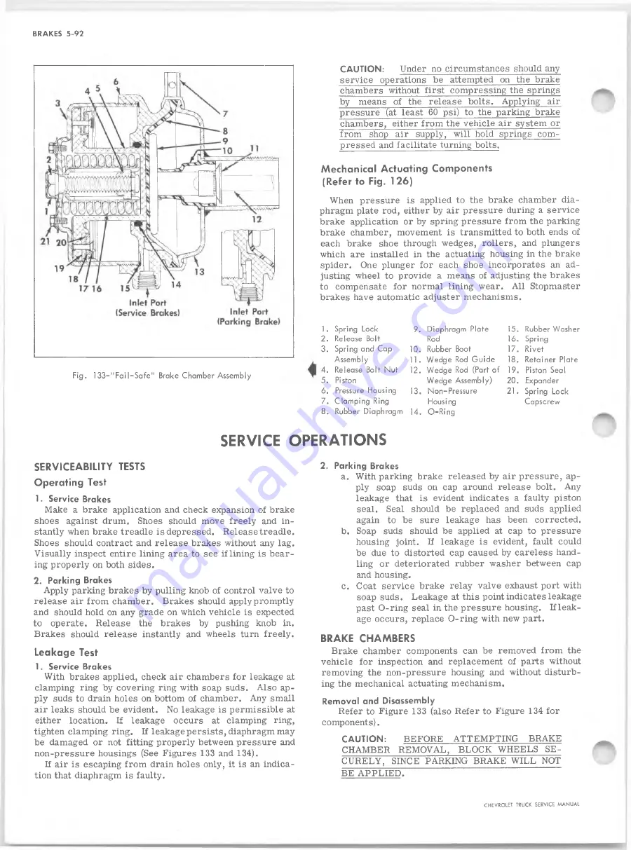
F ig . 1 3 3 -" F a il-S a fe " Brake Chamber Assembly
CA U TIO N :
Under no circumstances should any
service operations be attempted on the brake
chambers without first compressing the springs
by means of the release bolts. Applying air
pressure (at least 60 psi) to the parking brake
chambers, either from the vehicle air system or
from shop air supply, will hold springs com
pressed and facilitate turning bolts.
Mechanical Actuating Components
(Refer to Fig. 126)
When pressure is applied to the brake chamber dia
phragm plate rod, either by air pressure during a service
brake application or by spring pressure from the parking
brake chamber, movement is transmitted to both ends of
each brake shoe through wedges, rollers, and plungers
which are installed in the actuating housing in the brake
spider. One plunger for each shoe incorporates an ad
justing wheel to provide a means of adjusting the brakes
to compensate for normal lining wear. All Stopmaster
brakes have automatic adjuster mechanisms.
1
.
Spring Lock
9. Diaphragm Plate
15. Rubber Washer
2. Release Bolt
Rod
16. Spring
3. Spring and Cap
10. Rubber Boot
17. Rivet
Assembly
11. Wedge Rod G uid e
18. Retainer Plate
4. Release Bolt Nut
12. Wedge Rod (Part of
19. Piston Seal
5. Piston
Wedge Assembly)
20. Expander
6. Pressure Housing
13. Non-Pressure
21. Spring Lock
7. Clam ping Ring
Housing
Capscrew
8. Rubber Diaphragm
14. O -R in g
SERVICE OPERATIONS
SERVICEABILITY TESTS
Operating Test
1. Service Brakes
Make a brake application and check expansion of brake
shoes against drum. Shoes should move freely and in
stantly when brake treadle is depressed. Release treadle.
Shoes should contract and release brakes without any lag.
Visually inspect entire lining area to see if lining is bear
ing properly on both sides.
2. Parking Brakes
Apply parking brakes by pulling knob of control valve to
release air from chamber. Brakes should apply promptly
and should hold on any grade on which vehicle is expected
to operate. Release the brakes by pushing knob in.
Brakes should release instantly and wheels turn freely.
Leakage Test
1. Service Brakes
With brakes applied, check air chambers for leakage at
clamping ring by covering ring with soap suds. Also ap
ply suds to drain holes on bottom of chamber. Any small
air leaks should be evident. No leakage is permissible at
either location. If leakage occurs at clamping ring,
tighten clamping ring. If leakage persists, diaphragm may
be damaged or not fitting properly between pressure and
non-pressure housings (See Figures 133 and 134).
If air is escaping from drain holes only, it is an indica
tion that diaphragm is faulty.
2. Parking Brakes
a. With parking brake released by air pressure, ap
ply soap suds on cap around release bolt. Any
leakage that is evident indicates a faulty piston
seal. Seal should be replaced and suds applied
again to be sure leakage has been corrected.
b. Soap suds should be applied at cap to pressure
housing joint. If leakage is evident, fault could
be due to distorted cap caused by careless hand
ling or deteriorated rubber washer between cap
and housing.
c. Coat service brake relay valve exhaust port with
soap suds. Leakage at this point indicates leakage
past O-ring seal in the pressure housing. If leak
age occurs, replace O-ring with new part.
BRAKE CHAMBERS
Brake chamber components can be removed from the
vehicle for inspection and replacement of parts without
removing the non-pressure housing and without disturb
ing the mechanical actuating mechanism.
Rem oval and Disassembly
Refer to Figure 133 (also Refer to Figure 134 for
components).
CA U TIO N :
BEFORE ATTEMPTING BRAKE
CHAMBER REMOVAL, BLOCK WHEELS SE
CURELY, SINCE PARKING BRAKE W ILL NOT
BE APPLIED.
CHEVROLET TRUCK SERVICE MANUAL
Summary of Contents for 10 Series 1968
Page 1: ...ST 1 3 3 SB...
Page 3: ...w w...
Page 52: ...HEATER AND AIR CONDITIONING 1A 21 Fig 32 Charging Schematic CHEVROLET TRUCK SERVICE MANUAL...
Page 67: ......
Page 128: ...BODY IB 61 Fig 135 A uxiliary Seat CHEVROLET TRUCK SERVICE MANUAL...
Page 132: ...Fig 4 1 0 3 0 Series Truck Frame...
Page 133: ...Fig 5 4 0 6 0 Single A xle Truck Frame E x c Tilt Cab...
Page 135: ...Fig 7 4 0 6 0 Series Tilt Cab Truck Frames...
Page 139: ...w...
Page 169: ...fit w...
Page 233: ...I...
Page 248: ...BRAKES 5 15 TD 50 60 Fig 26 Parking Brake Cables T Models CHEVROLET TRUCK SERVICE MANUAL...
Page 347: ......
Page 389: ......
Page 393: ......
Page 411: ...ENGINE FUEL 6M 18 Fig 18A V 8 Typical CHEVROLET TRUCK SERVICE MANUAL...
Page 525: ......
Page 551: ......
Page 583: ...CHASSIS SHEET METAL 11 12 Fig 20 Designation and Name Plate CHEVROLET TRUCK SERVICE MANUAL...
Page 587: ...ELECTRICAL BODY AND CHASSIS 12 2 Fig 1 Fuse Panel CHEVROLET TRUCK SERVICE MANUAL...
Page 611: ...r ELECTRICAL BODY AND CHASSIS 12 26 9 CHEVROLET TRUCK SERVICE MANUAL...
Page 663: ......
Page 686: ...w...
Page 698: ...SPECIFICATIONS 12 ENGINE TORQUES CHEVROLET TRUCK SERVICE MANUAL...
Page 713: ...9...


