


CALREC
Putting Sound in the Picture
61
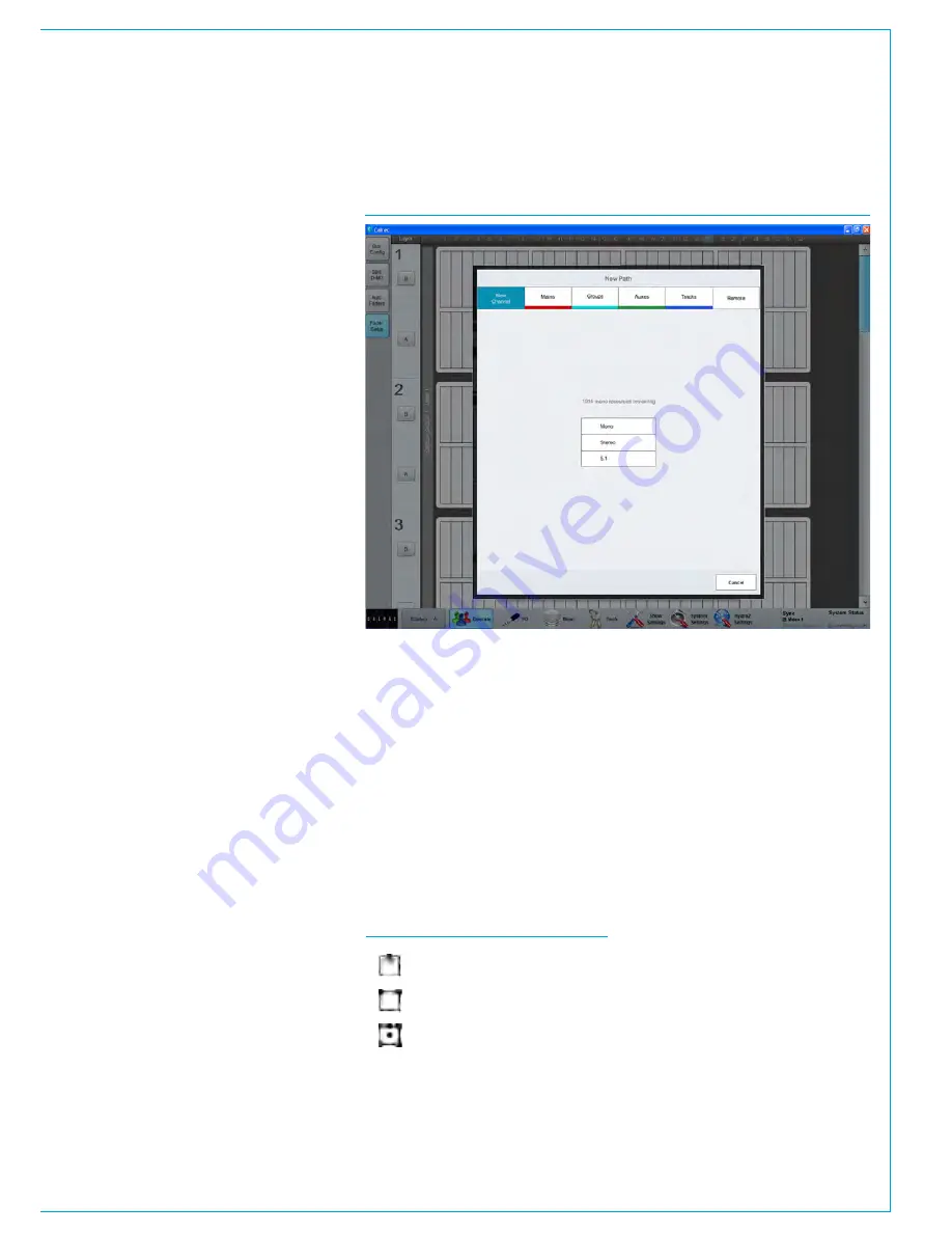
FADER SETUP SCREEN
Fader / path management can also be
carried out from the main application
GUI.
The
>Operate>Fader Setup
screen
provides a visual representation of all
faders and all layers, showing the current
path to fader assignment of the control
surface.
The on-screen display shows the type
of path (if any) assigned to each fader,
along with the input port / fader label, and
supporting indicators such as VCA group
status, layer locks, memory isolates, and
cloned paths.
Clicking on a fader cell will bring up the
options available:
If the fader currently has no path
assigned, a pop-up menu will allow path
allocation as shown in Fig 1.
If the selected fader already has a path
assigned, options will be presented to
create a clone, to move, or to delete the
path. If ‘Clone’ or ‘Move’ is selected, the
user should next select the destination
fader - where the clone will be placed, or
where the path is to be moved to.
When moving a path to a fader already
occupied by another path, the user is
presented with the option to swap the
position of the two paths over (same as
the Move Path function when performed
from the control surface), or to discard the
original path on the destination fader.
Operations can be performed on multiple
consecutive faders at the same time by
dragging, or shift-clicking to select a
group. Whole rows can be selected by
clicking the A / B layer markers down the
left hand side of the screen.
The fader setup screen now follows fader
access on the surface, in the same way
as the patching screen. This behaviour
can be toggled in the States button in the
left hand side of the footer of the main
application.
FIG 1 - MAIN APPLICATION, OPERATE>FADER SETUP SCREEN
FIG 2 - PATH WIDTH ICONS
- Mono
- Stereo
- 5.1 Surround
Memories from larger consoles
User shows / memories can be
transferred between mixing consoles of
the same type, for example, an Apollo
User Memory can be transferred to
another Apollo surface.
If a memory is loaded that was created
on a larger control surface, with more
faders, the additional paths are displayed
as virtual faders. The fader setup screen
can then be used to re-organise the paths
needed on to available physical faders /
layers.
The ICONS shown above in Fig 2 are
used to show the widths of various paths.
Assigning auxs and tracks to faders
in the Fader setup screen
From V7.0 it is now possible to assign
auxs and tracks to faders from the
Fader setup screen in the same way as
channels, groups and mains see Fig 1
above, these can also be assigned from
the Tools menu.
Remote Production Option
From V8.0 it is now possible to assign
remote paths from RP1 remote production
units by clicking on the ‘Remote’ option
as shown in Fig 1. This allows the
user to map the remote faders and
remote aux masters of RP1 units on
to the console surface. The operation
and integration of the RP1 remote
production unit with the Apollo console
is the subject of a separate manual :-
Remote Production RP1 System Manual
(926-222)
which can be downloaded
from the Calrec Website. In the manual
is a chapter ‘Operation Via Host Console’
which shows how to setup and operate
the RP1 remote production unit via a host
console in this case an Apollo .
Summary of Contents for Apollo
Page 7: ...calrec com Putting Sound in the Picture APOLLO INFORMATION...
Page 11: ...calrec com Putting Sound in the Picture APOLLO INTRODUCTION...
Page 16: ...16 APOLLO Digital Broadcast Production Console Introduction...
Page 17: ...calrec com Putting Sound in the Picture APOLLO CONTROL OVERVIEW...
Page 21: ...CALREC Putting Sound in the Picture 21 FIG 3 ROWS...
Page 36: ...Control Overview 36 APOLLO Digital Broadcast Production Console FIG 3 EXAMPLE LAYOUTS...
Page 40: ...40 APOLLO Digital Broadcast Production Console...
Page 41: ...calrec com Putting Sound in the Picture APOLLO CONTROL PANEL MODES...
Page 49: ...CALREC Putting Sound in the Picture 49 WILDABLE CONTROLS...
Page 52: ...52 APOLLO Digital Broadcast Production Console...
Page 53: ...calrec com Putting Sound in the Picture APOLLO GETTING SIGNALS INTO APOLLO...
Page 82: ...82 APOLLO Digital Broadcast Production Console Getting Signals into Apollo...
Page 83: ...calrec com Putting Sound in the Picture APOLLO PROCESSING AUDIO...
Page 110: ...110 APOLLO Digital Broadcast Production Console...
Page 111: ...calrec com Putting Sound in the Picture APOLLO ROUTING AUDIO...
Page 128: ...128 APOLLO Digital Broadcast Production Console...
Page 129: ...calrec com Putting Sound in the Picture APOLLO PASSING SIGNALS OUT OF APOLLO...
Page 137: ...calrec com Putting Sound in the Picture APOLLO MONITORING...
Page 152: ...152 APOLLO Digital Broadcast Production Console...
Page 153: ...calrec com Putting Sound in the Picture APOLLO COMMUNICATIONS...
Page 158: ...158 APOLLO Digital Broadcast Production Console...
Page 159: ...calrec com Putting Sound in the Picture APOLLO METERING...
Page 168: ...168 APOLLO Digital Broadcast Production Console...
Page 169: ...calrec com Putting Sound in the Picture APOLLO SHOWS MEMORIES AND PRESETS...
Page 183: ...calrec com Putting Sound in the Picture APOLLO CONSOLE FACILITIES...
Page 188: ...188 APOLLO Digital Broadcast Production Console...
Page 189: ...calrec com Putting Sound in the Picture APOLLO EXTERNAL INTERFACING...
Page 199: ...calrec com Putting Sound in the Picture APOLLO SYSTEM STATUS...
Page 202: ...202 APOLLO Digital Broadcast Production Console...
Page 203: ...calrec com Putting Sound in the Picture APOLLO GLOSSARY OF TERMINOLOGY...
Page 209: ...calrec com Putting Sound in the Picture APOLLO FEATURES BY SOFTWARE VERSION...


