CALREC
Putting Sound in the Picture
195
MIC OPEN SYSTEMS
Mic Open Systems are used to control
external devices, relative to the ‘on
air’ status of a signal source. Mic
open systems can CUT or DIM a loud
speaker feed to avoid feedback, or
control relays for switching purposes,
such as turning on ON AIR lights.
There are 5 mic open systems available
on the console, each is normally
associated with a physical area for control,
such as a studio or an area of a studio
floor. Mic open systems work for all input
ports, as microphones can be connected
to ports other than mic/line inputs.
Mic open systems detect whether the
assigned signal sources are on air.
A signal is deemed to be on air if:
• It is assigned to a channel input
(one or two).
• The channel is selected to that input
(one or two).
• Its fader is open and not cut.
• It is routed to a main output.
• That main output’s fader is open.
• If a signal is routed via a group or a
number of groups in series before
being routed to a main output, those
group faders must also be open and
not cut.
Note, the fader open trigger happens
at -90dB and the fader close trigger
happens at -95dB.
If a signal is routed to a console input via
a hydra2 patchbay and/or an input alias
the on air decoding will be the same as
described above.
When a mic open system detects that
a microphone is on air, it switches on
and the associated GPO/CUT/DIM is
executed.
Mic open systems are console-wide and
so do not split in line with user splits.
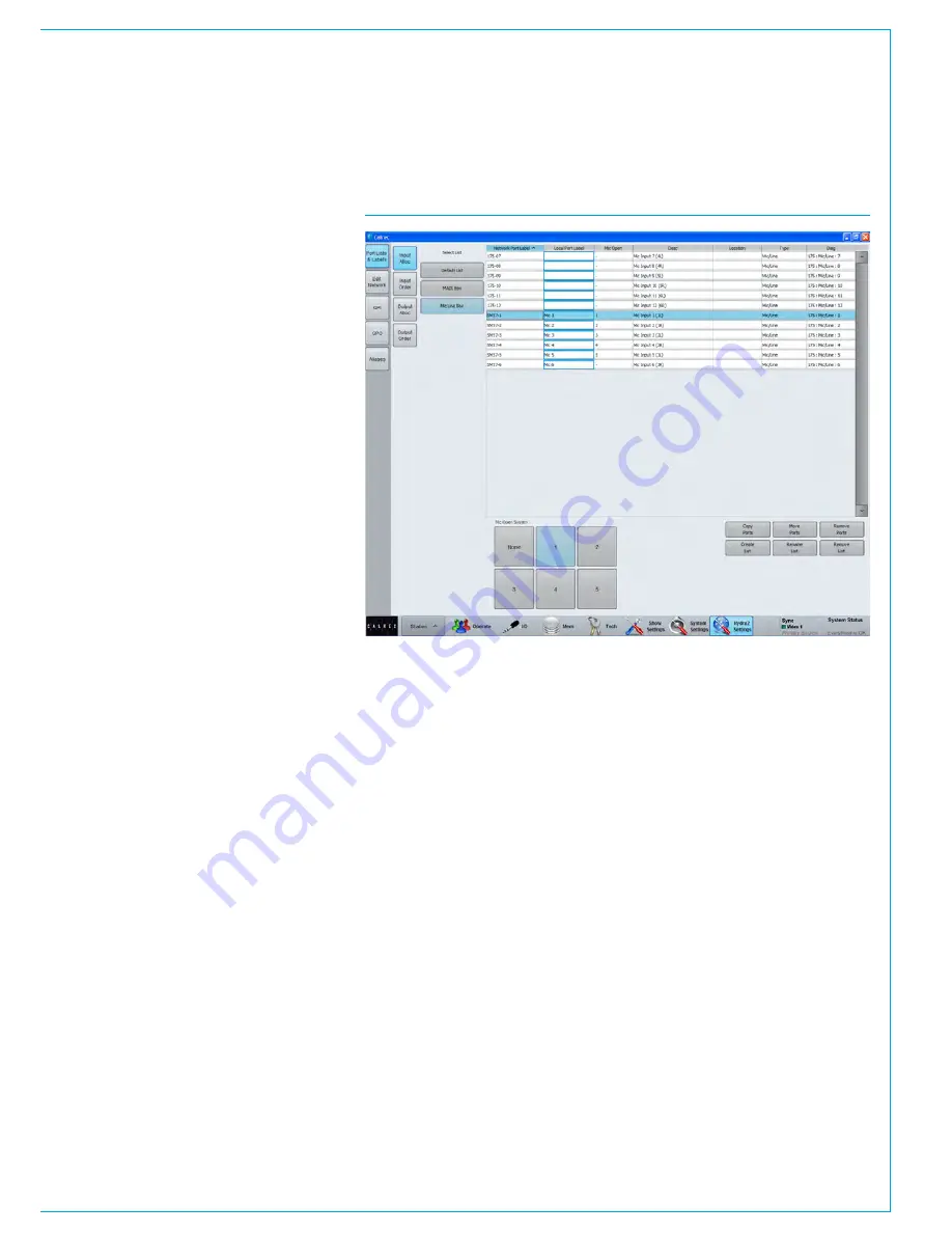
FIG 1 - ASSIGNING A MIC OPEN SYSTEM
Assigning Inputs to Mic Open
Systems
To allocate an input port to any of the
5 Mic Open Systems, select :
>Hydra2
Settings>Port Lists & Labels>Input Alloc
as shown in Fig 1.
There are 6 buttons at the bottom of the
input allocation window for assigning
inputs to any of the 5 mic open systems.
Select an input port list from the select
list down the left hand side of the window,
then select an input port from the list
and press one or more of the 5 mic
open system buttons - notice that the
corresponding cell in the 3rd column now
reflects your choice.
This is reflected in all screens where
inputs are displayed within the main
application. Within screens with limited
space the mic open column will be
labelled, ‘MO’.
Summary of Contents for Apollo
Page 7: ...calrec com Putting Sound in the Picture APOLLO INFORMATION...
Page 11: ...calrec com Putting Sound in the Picture APOLLO INTRODUCTION...
Page 16: ...16 APOLLO Digital Broadcast Production Console Introduction...
Page 17: ...calrec com Putting Sound in the Picture APOLLO CONTROL OVERVIEW...
Page 21: ...CALREC Putting Sound in the Picture 21 FIG 3 ROWS...
Page 36: ...Control Overview 36 APOLLO Digital Broadcast Production Console FIG 3 EXAMPLE LAYOUTS...
Page 40: ...40 APOLLO Digital Broadcast Production Console...
Page 41: ...calrec com Putting Sound in the Picture APOLLO CONTROL PANEL MODES...
Page 49: ...CALREC Putting Sound in the Picture 49 WILDABLE CONTROLS...
Page 52: ...52 APOLLO Digital Broadcast Production Console...
Page 53: ...calrec com Putting Sound in the Picture APOLLO GETTING SIGNALS INTO APOLLO...
Page 82: ...82 APOLLO Digital Broadcast Production Console Getting Signals into Apollo...
Page 83: ...calrec com Putting Sound in the Picture APOLLO PROCESSING AUDIO...
Page 110: ...110 APOLLO Digital Broadcast Production Console...
Page 111: ...calrec com Putting Sound in the Picture APOLLO ROUTING AUDIO...
Page 128: ...128 APOLLO Digital Broadcast Production Console...
Page 129: ...calrec com Putting Sound in the Picture APOLLO PASSING SIGNALS OUT OF APOLLO...
Page 137: ...calrec com Putting Sound in the Picture APOLLO MONITORING...
Page 152: ...152 APOLLO Digital Broadcast Production Console...
Page 153: ...calrec com Putting Sound in the Picture APOLLO COMMUNICATIONS...
Page 158: ...158 APOLLO Digital Broadcast Production Console...
Page 159: ...calrec com Putting Sound in the Picture APOLLO METERING...
Page 168: ...168 APOLLO Digital Broadcast Production Console...
Page 169: ...calrec com Putting Sound in the Picture APOLLO SHOWS MEMORIES AND PRESETS...
Page 183: ...calrec com Putting Sound in the Picture APOLLO CONSOLE FACILITIES...
Page 188: ...188 APOLLO Digital Broadcast Production Console...
Page 189: ...calrec com Putting Sound in the Picture APOLLO EXTERNAL INTERFACING...
Page 199: ...calrec com Putting Sound in the Picture APOLLO SYSTEM STATUS...
Page 202: ...202 APOLLO Digital Broadcast Production Console...
Page 203: ...calrec com Putting Sound in the Picture APOLLO GLOSSARY OF TERMINOLOGY...
Page 209: ...calrec com Putting Sound in the Picture APOLLO FEATURES BY SOFTWARE VERSION...


