CALREC
Putting Sound in the Picture
117
JOYSTICK PANNING
In addition to using the pan controls
in Send-Route, Strips and Wilds mode
(if assigned), panning can be achieved
using the joystick panel, if fitted.
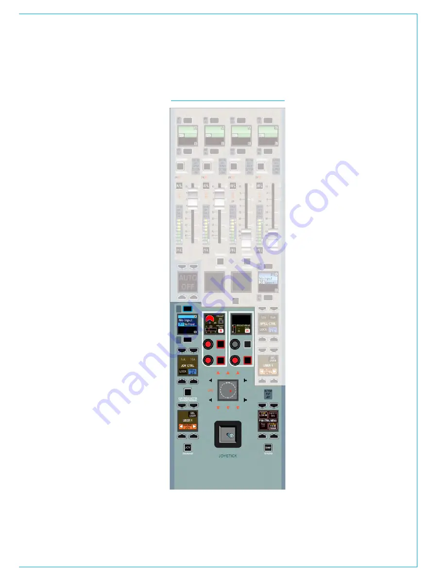
The panel is shown in Fig 1 with the
joystick controls highlighted. The upper
half of the panel containing the faders
functions in exactly the same way as
those on the monitor panel. The relevant
sections of this document for Surround
Spill, Downmixes, Main Paths on the Spill
Faders, should be referred to if these
functions are required.
Accessing the joystick controls
The information displayed on the joystick
controls relates to the path shown in
the upper left button cell display. This
display and its assign buttons function in
the same way as the fader label displays
above each fader. This path can be
selected in a number of ways.
Firstly, if the FOLL A/B button in the JOY
CTRL button cell is selected, the joystick
controls will follow the currently assigned
path. If FOLL A/B is deselected, the
controls will not follow the currently
assigned path. If selected, the controls
will follow the assigned path in the user
section displayed in the lower left button
cell. To change this user section, press
the SEL USER button and select a
different section.
The NUDGE JOY buttons in the lower
left button cell allow the joystick controls
to step up or down faders on the surface.
The upper assign display will reflect this
change to indicate which path is now
selected. If the FOLL A/B button is
selected, the NUDGE JOY buttons will
move the path assignment up and down
the faders too. If it is not selected, the
currently assigned path will remain the
same, but the joystick controls will control
a different path.
If the LOCK button in the JOY CTRL
button cell is pressed, the controls will
not affect any other path until they are
unlocked. Press the button again to
unlock.
Making the joystick controls active
When the required path has been
assigned, the joystick controls must
be made active. To do this, press the
CONTROLS ACTIVE button. The controls
can now be used to alter the pan position.
Disengaging the joystick
At any time, the joystick can be
disengaged to prevent accidental changes
to pan position. To do this, press the
DISENGAGE button. The rest of the
joystick controls remain active, and can be
interacted with.
Pan display
The pan display in the centre of the
joystick controls displays a range of
information. The hidden-till-lit loudspeaker
indicators provide an indication of the
widest path that is being panned to. Take
an example when panning to mains and
groups. If two main paths were of a 5.1
width and two were stereo width, the
loudspeaker indicators would appear as
they do in Fig 1, as 5.1 is the widest path
in this instance. The stereo buses would
receive a downmix of the 5.1 signal.
The red blob shows the position of the
audio in the sound field.
The white cross-hair indicates the physical
position of the joystick, which may not
necessarily be the same as the audio. For
example freezing an axis, panning only
to LR or disengaging the joystick can all
cause this situation to occur.
FIG 1 - JOYSTICK CONTROLS
Summary of Contents for Apollo
Page 7: ...calrec com Putting Sound in the Picture APOLLO INFORMATION...
Page 11: ...calrec com Putting Sound in the Picture APOLLO INTRODUCTION...
Page 16: ...16 APOLLO Digital Broadcast Production Console Introduction...
Page 17: ...calrec com Putting Sound in the Picture APOLLO CONTROL OVERVIEW...
Page 21: ...CALREC Putting Sound in the Picture 21 FIG 3 ROWS...
Page 36: ...Control Overview 36 APOLLO Digital Broadcast Production Console FIG 3 EXAMPLE LAYOUTS...
Page 40: ...40 APOLLO Digital Broadcast Production Console...
Page 41: ...calrec com Putting Sound in the Picture APOLLO CONTROL PANEL MODES...
Page 49: ...CALREC Putting Sound in the Picture 49 WILDABLE CONTROLS...
Page 52: ...52 APOLLO Digital Broadcast Production Console...
Page 53: ...calrec com Putting Sound in the Picture APOLLO GETTING SIGNALS INTO APOLLO...
Page 82: ...82 APOLLO Digital Broadcast Production Console Getting Signals into Apollo...
Page 83: ...calrec com Putting Sound in the Picture APOLLO PROCESSING AUDIO...
Page 110: ...110 APOLLO Digital Broadcast Production Console...
Page 111: ...calrec com Putting Sound in the Picture APOLLO ROUTING AUDIO...
Page 128: ...128 APOLLO Digital Broadcast Production Console...
Page 129: ...calrec com Putting Sound in the Picture APOLLO PASSING SIGNALS OUT OF APOLLO...
Page 137: ...calrec com Putting Sound in the Picture APOLLO MONITORING...
Page 152: ...152 APOLLO Digital Broadcast Production Console...
Page 153: ...calrec com Putting Sound in the Picture APOLLO COMMUNICATIONS...
Page 158: ...158 APOLLO Digital Broadcast Production Console...
Page 159: ...calrec com Putting Sound in the Picture APOLLO METERING...
Page 168: ...168 APOLLO Digital Broadcast Production Console...
Page 169: ...calrec com Putting Sound in the Picture APOLLO SHOWS MEMORIES AND PRESETS...
Page 183: ...calrec com Putting Sound in the Picture APOLLO CONSOLE FACILITIES...
Page 188: ...188 APOLLO Digital Broadcast Production Console...
Page 189: ...calrec com Putting Sound in the Picture APOLLO EXTERNAL INTERFACING...
Page 199: ...calrec com Putting Sound in the Picture APOLLO SYSTEM STATUS...
Page 202: ...202 APOLLO Digital Broadcast Production Console...
Page 203: ...calrec com Putting Sound in the Picture APOLLO GLOSSARY OF TERMINOLOGY...
Page 209: ...calrec com Putting Sound in the Picture APOLLO FEATURES BY SOFTWARE VERSION...


