CALREC
Putting Sound in the Picture
179
Once the required isolate elements
have been set, press the EXIT button on
the wild assign panel to return it to the
previously used mode.
Applying isolation scope to multiple
paths
Instead of applying the isolate settings
to just the assigned path, it is possible to
quickly apply the settings to a number of
paths at the same time.
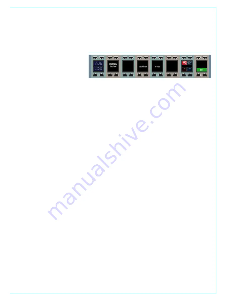
To do this, press the SET FLTR button on
the bottom row of the wild assign panel.
This will change the appearance of the
row to that shown in Fig 5. The elements
to be isolated can now be selected as
usual. Hold down the APPLY SEL button
and press the assign buttons of the paths
to which the settings should be applied.
While holding the APPLY SEL button,
the path assign buttons may be in one of
three states:
• Button not illuminated. The path has no
isolate elements applied to it.
• Button illuminated continuously. The
path already has some isolate elements
applied to it. Not necessarily the
current configuration of elements.
• Button illuminated but flashing. The
user has pressed the assign key to
assign the current configuration of
isolate elements to the path. If the
same assign button is pressed again,
it will return to one of the above states
depending on the path’s previous state.
Once the necessary changes have been
made the APPLY SEL button can be
released. To apply the settings press the
EXEC button, or to cancel them press the
CNCL button.
FIG 5 - WILD ASSIGN ROW IN SET FILTER MODE
Elements available for isolation
• Input 1 Settings
• Input 1 Ports
• Input 2 Settings
• Input 2 Ports
• EQ Bands 1-4
• EQ Bands 5-6
• Dynamics Unit 1 (comp/lim, exp/gate)
• Dynamics Unit 2 (comp/lim)
• Insert
• Fader Level and Settings
• VCA Master Fader
• VCA Slave
• Downmix
• Stereo Width
• Path Delay
• Pan to Mains and Groups
• Routing to Mains and Groups
• Track Send Pan
• Track Routing
• Aux Send Levels and Routing
• Mix Minus Routing
• Direct Output Levels
• Direct Output Ports
• Wilds
• Fader Wilds
Most of these settings are self
explanatory. The two which may require
further explanation are VCA Master Fader
and VCA Slave.
Isolating the VCA Master Fader element
isolates the fact that a fader is a VCA
master. If the fader is a master then any
memories loaded will not change the fact
that it is a master or alter any of its master
settings (level, cut).
Conversely, if the fader is not a master
and this element is isolated, any memories
loaded will not change it to become a
master. This element does not isolate
any slaves of the master in any way. If
all slaves of this master are removed by
a memory load, then the master has to
be removed by default. It cannot exist
without slaves. Also, if there is a slave
path on the same fader (see the VCA
Style Groups section for more details),
and all other slave faders are removed,
the master’s settings are coalesced onto
the same fader slave to preserve the mix
detail.
VCA Slave isolates the fact that the fader
is a slave. It maintains its link to a certain
master if that master still exists after a
memory load (the master must be isolated
individually). Similarly to the VCA Master
Fader element, it also prevents the fader
from becoming a slave due to a memory
load operation if it is not one already.
Summary of Contents for Apollo
Page 7: ...calrec com Putting Sound in the Picture APOLLO INFORMATION...
Page 11: ...calrec com Putting Sound in the Picture APOLLO INTRODUCTION...
Page 16: ...16 APOLLO Digital Broadcast Production Console Introduction...
Page 17: ...calrec com Putting Sound in the Picture APOLLO CONTROL OVERVIEW...
Page 21: ...CALREC Putting Sound in the Picture 21 FIG 3 ROWS...
Page 36: ...Control Overview 36 APOLLO Digital Broadcast Production Console FIG 3 EXAMPLE LAYOUTS...
Page 40: ...40 APOLLO Digital Broadcast Production Console...
Page 41: ...calrec com Putting Sound in the Picture APOLLO CONTROL PANEL MODES...
Page 49: ...CALREC Putting Sound in the Picture 49 WILDABLE CONTROLS...
Page 52: ...52 APOLLO Digital Broadcast Production Console...
Page 53: ...calrec com Putting Sound in the Picture APOLLO GETTING SIGNALS INTO APOLLO...
Page 82: ...82 APOLLO Digital Broadcast Production Console Getting Signals into Apollo...
Page 83: ...calrec com Putting Sound in the Picture APOLLO PROCESSING AUDIO...
Page 110: ...110 APOLLO Digital Broadcast Production Console...
Page 111: ...calrec com Putting Sound in the Picture APOLLO ROUTING AUDIO...
Page 128: ...128 APOLLO Digital Broadcast Production Console...
Page 129: ...calrec com Putting Sound in the Picture APOLLO PASSING SIGNALS OUT OF APOLLO...
Page 137: ...calrec com Putting Sound in the Picture APOLLO MONITORING...
Page 152: ...152 APOLLO Digital Broadcast Production Console...
Page 153: ...calrec com Putting Sound in the Picture APOLLO COMMUNICATIONS...
Page 158: ...158 APOLLO Digital Broadcast Production Console...
Page 159: ...calrec com Putting Sound in the Picture APOLLO METERING...
Page 168: ...168 APOLLO Digital Broadcast Production Console...
Page 169: ...calrec com Putting Sound in the Picture APOLLO SHOWS MEMORIES AND PRESETS...
Page 183: ...calrec com Putting Sound in the Picture APOLLO CONSOLE FACILITIES...
Page 188: ...188 APOLLO Digital Broadcast Production Console...
Page 189: ...calrec com Putting Sound in the Picture APOLLO EXTERNAL INTERFACING...
Page 199: ...calrec com Putting Sound in the Picture APOLLO SYSTEM STATUS...
Page 202: ...202 APOLLO Digital Broadcast Production Console...
Page 203: ...calrec com Putting Sound in the Picture APOLLO GLOSSARY OF TERMINOLOGY...
Page 209: ...calrec com Putting Sound in the Picture APOLLO FEATURES BY SOFTWARE VERSION...


