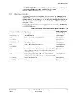
Level 2 Memory System
ARM DDI 0500D
Copyright © 2013-2014 ARM. All rights reserved.
7-6
ID021414
Non-Confidential
7.3
ACE master interface
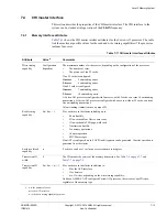
This section describes the properties of the ACE master interface. The ACE interface to the
system can be clocked at integer ratios of the
CLKIN
frequency.
7.3.1
Memory interface attributes
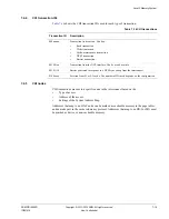
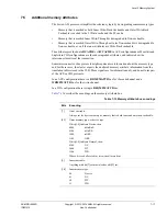
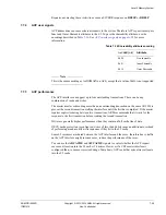
Table 7-5
shows the ACE master interface attributes for the Cortex-A53 processor. The table
lists the maximum possible values for the read and write issuing capabilities if the processor
includes four cores.
Table 7-5 ACE master interface attributes
Attribute
Value
a
Comments
Write issuing
capability
17 + n
The cluster can issue a maximum of 16 writes, excluding barriers:
•
Up to 16 writes to Normal memory that is both inner and outer write-back cacheable.
•
Up to 15 writes to all other memory types, including Device, Normal non-cacheable and
Write-through.
Any mix of memory types is possible, and each write can be a single write or a write burst.
Each core can also issue a barrier and the cluster can issue an additional barrier.
Read issuing
capability
8n + 4m + 1
8 for each core in the cluster including up to:
•
8 data linefills.
•
4 non-cacheable or Device data reads.
•
1 non-cacheable TLB page-walk read.
•
3 instruction linefills.
•
5 coherency operations.
•
1 barrier operation.
•
8 DVM messages.
Note
The 8 DVM messages per core can each be two part DVM messages, resulting in up to
16 DVM transactions per core.
If an ACP is configured, up to 4 ACP linefill requests can be generated. 1 barrier operation can
be generated from the cluster.
Exclusive thread
capability
n
Each core can have 1 exclusive access sequence in progress.
Write ID
capability
17 + n
The maximum number of outstanding write IDs is 21. This is the same as the maximum number
of outstanding writes.
Only Device memory types with nGnRnE or nGnRE can have more than one outstanding
transaction with the same AXI ID. All other memory types use a unique AXI ID for every
outstanding transaction.


