VD520 Series Inverter User Manual Parameter Description
- 155 -
deceleration is valid.
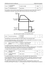
When the setting is effective and the running frequency is in the range of hopping frequency, the
actual running frequency will skip hopping frequency set boundary.
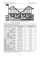
The following diagram is a schematic diagram of the hopping frequency effectively in the process of
acceleration and deceleration.
Hopping frequency range
Hopping
frequency 2
Hopping
frequency 2
Time(t)
Output
frequency(Hz)
Hopping frequency range
Hopping frequency range
Hopping frequency range
Fig 6-22 Effective schematic diagram of hopping frequency in the process of acceleration and deceleration
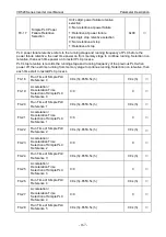
Fb-16
Frequency Detection
Value (FDT1)
0.00Hz~max frequency
50.00Hz
○
Fb-17
Frequency Detection
Lagged Value (FDTI)
0.0%~100.0% (FDT1 electrical level )
5.0%
○
Fb-18
Frequency Detection
Value (FDT2)
0.00Hz~max frequency
50.00Hz
○
Fb-19
Frequency Detection
Lagged Value (FDT2)
0.0%~100.0% (FDT2 electrical level )
5.0%
○
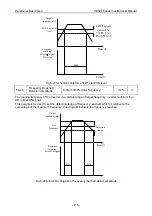
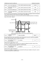
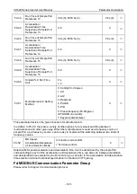
When the running frequency is higher than the frequency detecion values, the frequency converter
multi-function output DO output ON signal, and the frequency is lower than a certain frequency values
of the detection values, the DO output ON signal is cancelled.
The above parameters are used to set the detection value of output frequency, and cancel the lag
value of the output motion. Among them, the Fb-17 (Fb-19) is the percentage of lagging frequency
relative to the frequency detection values Fb- 6 (Fb-18). The diagram below for the FDT function.
Содержание VD520 Series
Страница 2: ......
Страница 9: ...VD520 Series Inverter User Manual Safety and Precautions 5 damage or performance reduce ...


