Parameter Description VD520 Series Inverter User Manual
- 122 -
Terminal
Set Value
Description
DIx
1
Running
DIy
2
(FWD/REV)
DIn
3
Three-line control mode 1
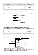
(1) When need to run, must be closed DIn terminals first, implemented by DIx or DIy pulse rising to
realize the motor forward or reverse control;
(2) When need to stop, it should be done by disconnect DIn terminal signal;
(3) The DIx, DIy, DIn is DI1 ~ DI5, HDI1 multi-function digital quantity input terminals, DIx, DIy for
pulse effectively, the DIn of level effectively;
External circuit
DIx
DIy
COM
FWD
REV
SB1
Digital command
end
DIn
Three-line control
model 1
SB2
SB3
VicRuns
Fig 6-11 Three-line control mode 1
SB1: Stop button SB2: Forward rotation button SB3: Forward rotation button
Three-line control mode 2: In this mode, Dln is enabled terminal, and the run command is given by
DIx, while the direction is determined by the status of DIy. Terminal function as below:
Terminal
Set Value
Description
DIx
1
Running
DIy
2
(FWD/REV)
DIn
3
Three-line control mode 2
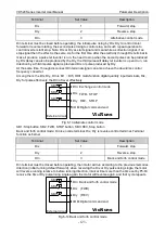
(1) When need to run, must be closed DIn terminals first, produced by DIx pulse rising along the
motor run signals, DIy status produce motor rotating direction signals.
(2) When need to stop, it should be done by disconnect DIn terminal signal.
(3) The DIx, DIy, DIn is DI1 ~ DI5, HDI1 multi-function input terminals, DIx for pulse effectively, DIy,
DIn for level effectively.
K
0
1
Command
FWD
REV
External circuit
DIx
DIy
COM
FWD
REV
SB1
Digital command
end
DIn
Three-line control
mode 2
SB2
K
VicRuns
Fig 6-12 Three-line control mode 2
SB1: Stop button SB2: Run button K: forward/reverse switchover
Alternative control mode: this mode Din as enabled terminal, run and the rotating direction and stop
are separately controlled by Din DIy alternatively. Terminal function as below:
Содержание VD520 Series
Страница 2: ......
Страница 9: ...VD520 Series Inverter User Manual Safety and Precautions 5 damage or performance reduce ...

