Parameter Description VD520 Series Inverter User Manual
- 118 -
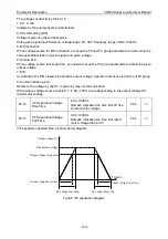
Vb
V1
f1
fb
Output voltage
Output frequency
V1
:
Manual torque boost voltage
Vb
:
Max output voltage
f1
:
Manual torque boost cutoff frequency
fb
:
Rated running frequency
V1: manual torque boost voltage Vb: max output voltage
f1: manual torque boost cutoff frequency fb: rated running frequency
Fig 6-6 Manual torque boost diagram
F4-04
MS VF Frequency Point 1
0.00Hz~F4-05
0.00Hz
◎
F4-05
MS VF Voltage Point 1
0.0%~100.0%
0.0%
◎
F4-06
MS VF Frequency Point 2
F4-04~F4-07
0.00Hz
◎
F4-07
MS VF Voltage Point 2
0.0%~100.0%
0.0%
◎
F4-08
MS VF Frequency Point 3
F4-05~Rated motor frequency (F2-04)
0.00Hz
◎
F4-09
MS VF Voltage Point 3
0.0%~100.0%
0.0%
◎
F4-03~F4-08 six parameters defined multistage V/F curve.
The curve of multipoint V/F should set according to the motor load characteristic, what need note is,
the relationship between the three point voltage and frequency points must be satisfied: V1<V2<V3,
F1<F2<F3. Figure 6-7 is multipoint V/F curve set diagram.
Voltage%
Vb
V3
V2
V1
F1
F2
F3
Fb
Frequency%
V1-V3: MS speed V/F voltage percentage of 1-3 section
F1-F3: MS speed V/F voltage percentage of 1-3 section
Vb: rated motor voltage Fb: rated motor running frequency
Fig 6-7 Multipoint V/F curve set diagram
Voltage set too high may lead to motor overheating or even burning when low frequency, frequency
inverter may be loss of speed or overcurrent protection.
Содержание VD520 Series
Страница 2: ......
Страница 9: ...VD520 Series Inverter User Manual Safety and Precautions 5 damage or performance reduce ...


