VD520 Series Inverter User Manual Parameter Description
- 101 -
In addition, when the frequency source selection for the main and auxiliary operation, can be set the
offset frequency through F0-08, superimposed offset frequency on the main and auxiliary operation
result in a flexible response to all kinds of needs.
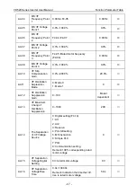
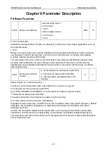
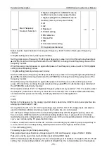
F0-06
Auxiliary Frequency
Source B Range
Reference Selection
when Superimposed
1: Relative to the max frequency
2: Relative to frequency source A
0
○
F0-07
Auxiliary Frequency
Source B Range
when Superimposed
0%~150%
100%
○
When
selecting frequency source for the “frequency superposition” (F0-05 set to 1, 3 or 4), these two
parameters used to determine the adjusting range of auxiliary frequency source.
F0-06 is used to determine the relative object of the scope of the auxiliary frequency source, can
select to the relative to the maximum frequency, can also be relative to the main frequency source A,
if the selection is relative to the main frequency source, the scope of the auxiliary frequency source
will change as main frequency source A change.
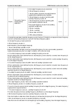
F0-08
Auxiliary
Frequency
Source Offset
Frequency when
Superimposed
0.00Hz~max frequency F0-10
0.00Hz
○
This function code is only valid at the time of frequency source selection of the main and auxiliary
operation.
When the frequency source is main and auxiliary operation, F0-08 as offset frequency, and with main
and auxiliary operation result superimposed as the final frequency set value, make the frequency set
can be more flexible.
F0-09
Digital Setting
Frequency
0.00Hz~max frequency (F0-10)
50.00Hz
○
When frequency source selection
as “digital setting” or “terminal UP/DOWN”, the function code value
is the initial value of frequency digital setting of inverter.
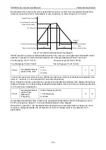
F0-10
Max Frequency
50.00Hz~600.00Hz
50.00Hz
◎
VD520 analog input, pulse input (HDI1), multi-reference etc., 100% of their relative to F0-10 scaling
as frequency source.
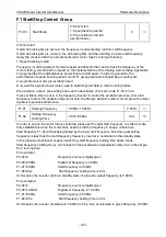
F0-11
Frequency Upper
Limit Source
0: F0-12 setting
1: AI1
2: AI2
3: Reserved
4: PULSE setting
5: Communication setting
0
◎
Define the frequency upper limit source. Frequency upper limit can be from digital setting (F0-12),
also from the analog input channel. When use analog input set the frequency upper limit, 100% of the
analog input set corresponding F0-12.
For example at the scene of the winding control using torque control mode, in order to avoid material
break appear “galloping” phenomenon, can use analog set the frequency upper limit, when inverter
running to the frequency upper limit value, the frequency inverter in frequency upper limit running.
Содержание VD520 Series
Страница 2: ......
Страница 9: ...VD520 Series Inverter User Manual Safety and Precautions 5 damage or performance reduce ...

