VD520 Series Inverter User Manual Function Parameter Table
- 85 -
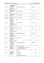
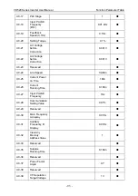
A3-07
Speed Loop
Filter Time
Constant
0.000s~0.100s
0.000s
○
A3-09
Motor Torque
Upper Limit
Source
0: Encode F3-10 setting
1: AI1
2: AI2
3: AI3
4: PULSE setting
5: Communication setting
6: MIN (AI1, AI2)
7: MAX (AI1, AI2)
The full scale of options 1~7
corresponding to the F3-10
0
○
A3-10
Digital Setting
for Motor Torque
Upper Limit
0%~200.0%
150.0%
○
A3-11
Brake Torque
Upper Limit
Source
0: Encode F3-12 setting
1: AI1
2: AI2
3: AI3
4: PULSE setting
5: Communication setting
6: MIN (AI1, AI2)
7: MAX (AI1, AI2)
The full scale of options 1~7
corresponding to the F3-12
0
○
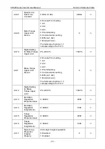
A3-12
Digital Setting
for Brake
Torque Upper
Limit
0%~200.0%
150.0%
○
A3-13
Excitation
Regulation
Proportion Gain
0~60000
2000
○
A3-14
Excitation
Regulation
Integral Gain
0~60000
1300
○
A3-15
Torque
Regulation
Proportion Gain
0~60000
2000
○
A3-16
Torque
Regulation
Integral Gain
0~60000
1300
○
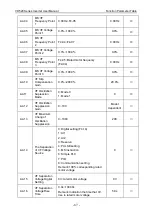
A3-17
Speed Loop
Proportion
Integral
Property
Unit’s digit: Integral separation
0: Disabled
1: Enabled
0
○
Содержание VD520 Series
Страница 2: ......
Страница 9: ...VD520 Series Inverter User Manual Safety and Precautions 5 damage or performance reduce ...


