Function Parameter Table VD520 Series Inverter User Manual
- 68 -
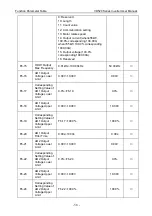
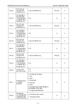
Source
1: AI1
2: AI2
3: Reserved
4: PULSE setting
5: Communication setting
6: Multi-reference setting
7: Keypad potentiometer
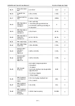
FA-01
PID Digital
Giving
0.0%~100.0%
50.0%
○
FA-02
PID Feedback
Source
0: A1
1: AI2
2: Reserved
3: AI1-AI2
4: PULSE setting
5: Communication setting
6: AI1+AI2
7: MAX (IAI1I, IAI2I)
8: MIN (IAI1I, IAI2I)
0
○
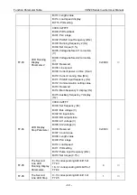
FA-03
PID Action
Direction
0: Positive action
1: Anti-action
0
○
FA-04
PID Given
Feedback
Range
0~65535
1000
○
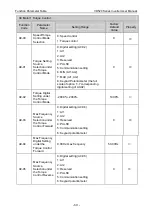
FA-05
Proportion Gain
Kp1
0.0~100.0
20.0
○
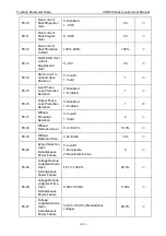
FA-06
Integral Time
Ti1
0.01s~10.00s
2.00s
○
FA-07
Differential Time
Td1
0.000s~10.000s
0.000s
○
FA-08
PID Reverse
Cut-off
Frequency
0.00~max frequency
0.00Hz
○
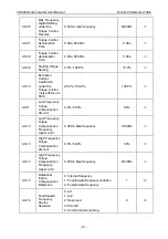
FA-09
PID Deviation
Limit
0.0%~100.0%
0.0%
○
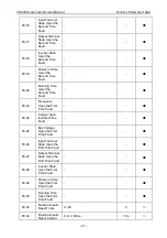
FA-10
PID Differential
Limiting
0.00%~100.00%
0.10%
○
FA-11
PID Given
Change Time
0.00s~650.00s
0.00s
○
FA-12
PID Feedback
Filter Time
0.00s~60.00s
0.00s
○
FA-13
PID Output
Filter Time
0.00s~60.00s
0.00s
○
Содержание VD520 Series
Страница 2: ......
Страница 9: ...VD520 Series Inverter User Manual Safety and Precautions 5 damage or performance reduce ...


