VD520 Series Inverter User Manual Function Parameter Table
- 55 -
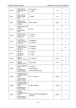
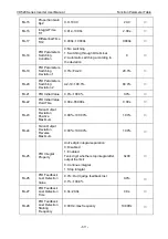
F5-23
Corresponding
Setting of AI Curve
1 Min Input
-100.0%~+100.0%
0.0%
○
F5-24
AI Curve 1 Max
Input
F5-22~+10.00V
10.00V
○
F5-25
Corresponding
Setting of AI Curve
1 Max Input
-100.0%~+100.0%
100.0%
○
F5-26
AI 1 Filter Time
0.00s~10.00s
0.10s
○
F5-27
AI Curve 2 Min
Input
-10.00V~F5-29
0.00V
○
F5-28
Corresponding
Setting of AI Curve
2 Min Input
-100.0%~+100.0%
0.0%
○
F5-29
AI Curve 2 Max
Input
F5-27~+10.00V
10.00V
○
F5-30
Corresponding
Setting of AI Curve
2 Max Input
-100.0%~+100.0%
100.0%
○
F5-31
AI 2 Filter Time
0.00s~10.00s
0.10s
○
F5-32
AI Curve 3 Min
Input
-10.00V~F5-34
0.00V
○
F5-33
Corresponding
Setting of AI Curve
3 Min Input
-100.0%~+100.0%
0.0%
○
F5-34
AI Curve 3 Max
Input
F5-32~+10.00V
10.00V
○
F5-35
Corresponding
Setting of AI Curve
3 Max Input
-100.0%~+100.0%
100.0%
○
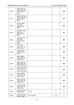
F5-37
Pulse Min Input
0.00kHz~F5-39
0.00kHz
○
F5-38
Corresponding
Setting of Pulse
Min Input
-100.0%~+100.0%
0.0%
○
F5-39
Pulse Max Input
F5-37~100.00kHz
50.00kHz
○
F5-40
Corresponding
Setting of Pulse
Max Input
-100.0%~+100.0%
100.0%
○
F5-41
PULSE Filter Time
0.00s~10.00s
0.10s
○
F5-42
Travel Switch Lock
Time
0.00s~10.00s
1.00s
○
Содержание VD520 Series
Страница 2: ......
Страница 9: ...VD520 Series Inverter User Manual Safety and Precautions 5 damage or performance reduce ...


