Fault Shooting and Solutions VD520 Series Inverter User Manual
- 194 -
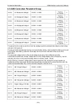
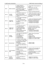
Err.11
Motor overload
1. Motor protection
parameters F8-01 set
whether appropriate
2. Whether the load is too
large or motor stalling
3. Small frequency converter
selection
1. Three-phase input power is not
normal
2. Drive board abnormal
3. Lightning protection plate
abnormal
4. Main control board abnomal
Err.12
Inverter
overload
1. Whether the load is too
large or motor stalling
2. Small frequency converter
selection
1. Reduce the load and check the
motor and mechanical conditions
2. Selection inverter with bigger
class power
Err.13
Input side
phase loss
1. Three-phase input power
is not normal
2. Drive board abnormal
3. Lightning protection plate
abnormal
4. Main control board
abnomal
1. Check and eliminate the problems
existing in the peripheral circuit
2. Seeking technical support
3. Seeking technical support
4. Seeking technical support
Err.14
Output side
phase loss
1. The lead of inverter to
motor is not normal
2. Inverter three-phase
output imbalance when
motor running
3. Driven board abnormal
4. Module abnormal
1. Eliminate peripheral failure
2. Check the motor three-phase
winding is normal and
troubleshooting
3. Seeking technical support
4. Seeking technical support
Err.15
Module
overheat
1. Environment temperature
is too high
2. Air duct blockage
3. Fan damage
4. Module thermal
resistance damage
5. Inverter module damage
1. Reduce the environmental
temperature
2. Clean air duct
3. Replace the fan
4. Replace the thermal resistance
5. Replace the inverter module
Err.17
External fault
1. Through the multi-function
terminal DI input external
fault signal
2. Through the virtual IO
function input external fault
signal
1. Reset running
2. Reset running
Err.18
Communication
fault
1. The PC work is not work
2. Communication line is not
normal
3. Communication
expansion card F0-23 set is
not correct
4. Communication
parameter Fd group is not
correct
1. Check the PC connection line
2. Check the communication
connection line
3. Correctly set up communication
expansion card type
4. Correctly set communication
parameters
Err.19
Current
detection
abnormal
1. Check the hall device
abnormal
2. Driver board abnormal
1.
Replace the hall device
2. Replace the driver board
Содержание VD520 Series
Страница 2: ......
Страница 9: ...VD520 Series Inverter User Manual Safety and Precautions 5 damage or performance reduce ...

