Function Blocks
UM353-1B
April
2012
3-34
3.2.27 DIE_ - Digital Input - Ethernet
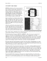
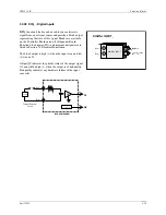
DIE_ function blocks use Modbus command 04
“Read Input Registers” to enable the controller to
read digital data from other stations over the
Ethernet network.
Up to 32 DIE_ blocks are available. Blocks are
assigned in sequence, controller wide, with each
use. Digital data is On/Off data packed into a 16-bit
word. This data is fanned out to block outputs D0 –
DF.
The IP ADRES parameter is used to configure the
IP address of the source device. The MB ADRES
parameter allows a Modbus address to be
configured. When connecting to other Siemens 353
controllers, the Modbus address is set to 1. In some
cases, other devices may use a different address or,
when going through a Modbus/TCP gateway, a
Modbus network may have multiple devices, each
having a unique address.
The MB REG parameter identifies the location of the digital data in the source device. The REG TYP parameter
enables reading of Holding Registers (Modbus Function Code 03) or Input Registers (Modbus Function Code 04).
Both are treated the same in most Modbus devices but the Input type is the most common usage. The use of DOE
blocks in other Siemens 353 controllers as the input source is defined by using the Modbus Registers from the table
below. The UD RATE parameter configures the rate at which the block will request data. The P2P setting will
update the data at the rate set by the P2P RATE parameter in the ETHERNET block. The Ct setting will update the
data at the cycle time of the controller.
Output QS indicates the quality of the received data and will go high (1) when the data is bad. This is normally
associated with failure to receive data due to a communication failure or a misconfiguration of the source.
FB
Number
MB
Register
FB
Number
MB
Register
FB
Number
MB
Register
FB
Number
MB
Register
DOE01 31025 DOE09 31033 DOE17 31041 DOE25 31049
DOE02 31026 DOE10 31034 DOE18 31042 DOE26 31050
DOE03 31027 DOE11 31035 DOE19 31043 DOE27 31051
DOE04 31028 DOE12 31036 DOE20 31044 DOE28 31052
DOE05 31029 DOE13 31037 DOE21 31045 DOE29 31053
DOE06 31030 DOE14 31038 DOE22 31046 DOE30 31054
DOE07 31031 DOE15 31039 DOE23 31047 DOE31 31055
DOE08 31032 DOE16 31040 DOE24 31048 DOE32 31056
Note: Registers listed are Extended Modbus Registers. Not all Modbus devices support them
DIGITAL INPUTS 16 CHAN - ETHERNET
DIGITAL INPUTS
DIE_
16-CHAN ETHERNET
D0
Output
D0
DF
Output
DF
QS
Output
QS
E
th
e
rn
et
N
e
tw
or
k
IP AD
d
RES
s
(H)
....
nnn.nnn.nnn.nnn
(192.168.0.0)
MB
REG
ister
(H)
............. 1 - 65535
(1)
P
A
R E S
I
D
A D R
E
S
B
M
MB AD
d
RES
s
(H)
............... 0 - 255
(1)
M B
R
E
G
Y
R E G
T
P
REG
ister
TYPE
(H)
.
InPut
/
Hold
ing
(InPut)
T E
A
R
D
U
U
p
D
ate
RATE
(H)
............. P2P/Ct
(P2P)
E
Содержание 353
Страница 12: ...Contents UM353 1B x April 2012 ...
Страница 22: ...Introduction UM353 1B April 2012 1 10 ...
Страница 30: ...Configuration Overview UM353 1B April 2012 2 8 ...
Страница 122: ...Function Blocks UM353 1B April 2012 3 92 ...
Страница 168: ...Data Mapping UM353 1B April 2012 6 28 ...
Страница 204: ...Controller and System Test UM353 1B April 2012 9 8 ...
Страница 222: ...Calibration UM353 1B April 2012 11 4 ...
Страница 226: ...Circuit Description UM353 1B April 2012 12 4 ...
Страница 238: ...Model Designation and Specifications UM353 1B April 2012 13 12 EC Declaration of Conformity ...
Страница 239: ...UM353 1B Model Designation and Specifications April 2012 13 13 Annex A to the EC Declaration of Conformity ...
Страница 240: ...Model Designation and Specifications UM353 1B April 2012 13 14 ...
Страница 244: ...Abbreviations And Acronyms UM353 1B 14 4 April 2012 ...


