UM353-1B
Contents
April 2012
v
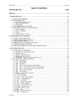
12.1 OVERVIEW .............................................................................................................................................. 12-1
12.2 MPU CONTROLLER BOARD ................................................................................................................ 12-2
12.3 I/O EXPANDER BOARD......................................................................................................................... 12-3
13.0 MODEL DESIGNATION AND SPECIFICATIONS ................................................................................ 13-1
13.1 MODEL DESIGNATION ......................................................................................................................... 13-1
13.2 ACCESSORIES......................................................................................................................................... 13-3
13.3 SERVICE PARTS KITS ........................................................................................................................... 13-3
13.4 MECHANICAL SPECIFICATIONS ........................................................................................................ 13-5
13.5 POWER INPUT REQUIREMENTS......................................................................................................... 13-5
13.6 MPU CONTROLLER BOARD SPECIFICATIONS................................................................................ 13-5
13.7 I/O EXPANDER BOARD SPECIFICATIONS ........................................................................................ 13-6
13.8 ENVIRONMENTAL SPECIFICATIONS ................................................................................................ 13-9
13.8.1 Standard Mounting............................................................................................................................ 13-9
13.8.2 Enclosure Mounting.......................................................................................................................... 13-9
13.8.3 Electromagnetic Compatibility (EMC) ............................................................................................. 13-9
13.9 AGENCY APPROVALS ........................................................................................................................ 13-10
13.9.1 CSA Hazardous Locations Precautions .......................................................................................... 13-10
13.9.2 Special Conditions for Safe Use ..................................................................................................... 13-11
14.0 ABBREVIATIONS AND ACRONYMS ..................................................................................................... 14-1
SOFTWARE RELEASE MEMO
LIST OF ILLUSTRATIONS
FIGURE AND TITLE
PAGE
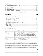
1-1 Siemens 353, Exploded View ............................................................................................................................ 1-2
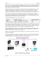
1-2 Ethernet Architecture Example .......................................................................................................................... 1-3
2-1 Configuration Road Map.................................................................................................................................... 2-6
2-2 MultiMediaCard Road Map ............................................................................................................................... 2-7
3-1 PCOM Logic .................................................................................................................................................... 3-69
7-1 Cover Installation and Removal......................................................................................................................... 7-4
7-2 Panel Cutout Dimensions ................................................................................................................................... 7-4
7-3 Siemens 353 Dimensions ................................................................................................................................... 7-5
7-4 Case Mounting Clip ........................................................................................................................................... 7-5
7-5 Rear Terminal Layout and Terminal Assignments............................................................................................. 7-8
7-6 Analog Input AIN1, 2-Wire Transmitter.......................................................................................................... 7-10
7-7 Analog Inputs AIN1, 2, and 3; 4-Wire Transmitters........................................................................................ 7-11
7-8 Universal Analog Input AINU1 ....................................................................................................................... 7-11
7-9 Analog Output AOUT 1, Current Output ........................................................................................................ 7-12
7-10 Analog Output AOUT1, Voltage Output ....................................................................................................... 7-12
7-11 Digital Inputs DIN and DINU........................................................................................................................ 7-13
7-12 Digital Output DOUT1, Resistive and Inductive Loads ................................................................................ 7-14
7-13 Universal Analog Input AINU1, Thermocouple Input .................................................................................. 7-15
7-14 Reference Junction Lead Formation .............................................................................................................. 7-15
7-15 Universal Analog Input AINU1; 2, 3, and 4-Wire RTD Inputs..................................................................... 7-16
7-16 Universal Analog Input, AINU1 Shown........................................................................................................ 7-17
7-17 Universal Relay Outputs ROUT1 and 2, Resistive Load ............................................................................... 7-17
7-18 Modbus Communications, 353 to APACS™ ACM or Personal Computer................................................... 7-19
7-19 Model 353 to Siemens SIREC D Recorder Analog Input Wiring ................................................................. 7-20
7-20 Controller Power Wiring................................................................................................................................ 7-20
7-21 Suggested Power Wiring................................................................................................................................ 7-21
7-22 Daisy Chained Power Wiring......................................................................................................................... 7-21
8-1 Chart 1, Autotune ............................................................................................................................................... 8-5
Содержание 353
Страница 12: ...Contents UM353 1B x April 2012 ...
Страница 22: ...Introduction UM353 1B April 2012 1 10 ...
Страница 30: ...Configuration Overview UM353 1B April 2012 2 8 ...
Страница 122: ...Function Blocks UM353 1B April 2012 3 92 ...
Страница 168: ...Data Mapping UM353 1B April 2012 6 28 ...
Страница 204: ...Controller and System Test UM353 1B April 2012 9 8 ...
Страница 222: ...Calibration UM353 1B April 2012 11 4 ...
Страница 226: ...Circuit Description UM353 1B April 2012 12 4 ...
Страница 238: ...Model Designation and Specifications UM353 1B April 2012 13 12 EC Declaration of Conformity ...
Страница 239: ...UM353 1B Model Designation and Specifications April 2012 13 13 Annex A to the EC Declaration of Conformity ...
Страница 240: ...Model Designation and Specifications UM353 1B April 2012 13 14 ...
Страница 244: ...Abbreviations And Acronyms UM353 1B 14 4 April 2012 ...


