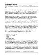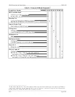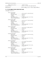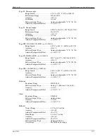
Model Designation and Specifications
UM353-1B
April
2012
13-8
Millivolt Overvoltage
Case Rear Terminals
AINU1
Case Rear Terminals
AINU2
Maximum
46 to 47
50 to 51
+/- 30 Vdc
45 to 47
48 to 47
49 to 51
52 to 51
+5/-0.7 Vdc
45, 46, 47, or 48 to
station common
49, 50, 51, or 52 to
station common
+/- 30 Vdc
Analog Input: (1)
Input Range ...................................................0-5 Vdc (standard calibration 1-5 Vdc)
Zero.................................................0-1
Vdc
Span ................................................4-5
Vdc
Type
........................................................Single
ended
Accuracy
......................................................0.10
%
Resolution
....................................................0.024
%
Software Output Type ...................................Analog [configurable (default 0.0 - 100.0)]
Normal Mode Rejection ................................>50dB @ 60Hz.
Input Impedance............................................>1 megohm
Maximum Continuous Input .........................+/-30 Vdc
Analog Output: (1)
Standard Calibration......................................4-20 mAdc
Zero.................................................4 mAdc +/- trim
Span ................................................16 mAdc +/- trim
Accuracy
......................................................0.10
%
Resolution
....................................................0.003
%
Software Input Type......................................Analog [configurable (default 0.0 - 100.0)]
Current Range Limits ....................................2.4 to 21.6 mA dc
Signal Reference ...........................................Neg. (-) output tied to station common
Output Load ..................................................800 Ohms
Overvoltage Protection..................................30 Vdc
Digital Input: (1)
Logic “1” Range............................................15-30 Vdc
Logic “0” Range............................................0-1 Vdc
Overvoltage ...................................................+/-30
Vdc
Minimum Required ON Time .......................>Scan Time
Software
Output Type ...................................Digital
Isolation.........................................................100
Vdc
Universal Digital Inputs: (2)
Logic “1” Range............................................4-30 Vdc
Input Current .................................................<7 mA @ 30 V
Logic “0” Range............................................0-1 Vdc
Overvoltage ...................................................+/-30
Vdc
Frequency Range...........................................0 to 25,000 Hz.
Accuracy .......................................................0.03 % of reading
Minimum
Operating
Frequency ....................0.05 Hz.
Pulse
Width ...................................................20
μ
sec (minimum)
Signal Types..................................................Sine Square, Pulse, Triangle, or Contact Closure
(contacts
require external power)
Содержание 353
Страница 12: ...Contents UM353 1B x April 2012 ...
Страница 22: ...Introduction UM353 1B April 2012 1 10 ...
Страница 30: ...Configuration Overview UM353 1B April 2012 2 8 ...
Страница 122: ...Function Blocks UM353 1B April 2012 3 92 ...
Страница 168: ...Data Mapping UM353 1B April 2012 6 28 ...
Страница 204: ...Controller and System Test UM353 1B April 2012 9 8 ...
Страница 222: ...Calibration UM353 1B April 2012 11 4 ...
Страница 226: ...Circuit Description UM353 1B April 2012 12 4 ...
Страница 238: ...Model Designation and Specifications UM353 1B April 2012 13 12 EC Declaration of Conformity ...
Страница 239: ...UM353 1B Model Designation and Specifications April 2012 13 13 Annex A to the EC Declaration of Conformity ...
Страница 240: ...Model Designation and Specifications UM353 1B April 2012 13 14 ...
Страница 244: ...Abbreviations And Acronyms UM353 1B 14 4 April 2012 ...


