


Installation
UM353-1B
April
2012
7-18
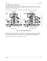
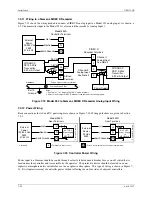
7.4.9 Modbus Wiring
This section describes the wiring needed to connect a host device to a Siemens 353’s Modbus network interface.
When connected, the host can read data from and write data to a Siemens 353 in a command/response format.
Most host devices communicate using RS232 while the Modbus network interface is RS485. As shown in Figure 7-
18, a 2-wire RS485 to RS232 converter is installed to perform the protocol conversion and adapt the connection
hardware. A shielded RS232 cable with either DB9 or DB25 connectors is installed between the host device and
the converter. An RS485 shielded, twisted-pair cable connects the converter to a Siemens 353. Up to 32 Siemens
353s can be connected since RS485 is a multi-drop network.
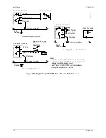
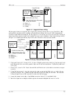
Shown below are the jumper locations and identifiers for the Entrelec® Isolated Converter shown in Figure 7-18.
Rt (INT1)
R (INT2)
E (INT3)
For access to jumpers
carefully remove the side
of the module that has the
jumper label.
Entrelec ILPH 084.233.11 Isolated Converter
RS485 link on
one pair
A
G
00336
a
120
Ω
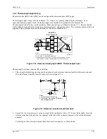
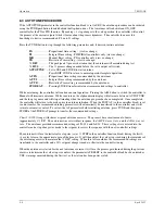
7.4.10 Ethernet Wiring
A sample architecture and a brief description are
presented in the Introduction section of this manual. An
RJ-45 Ethernet connector is located on the back of the
case. Ethernet cables external to the controller must be
rated Category 5 or better. Shielded cable or the use of
fiber optic transmission is highly recommended outside
the panel or cabinet, as shown at right. Many Ethernet
switches offer fiber optic ports as an option.
Model 353
with Ethernet
Model 353
with Ethernet
Model 353
with Ethernet
Hub or
Switch
Industrial Ethernet
Shielded Cable
Siemens Industrial
Ethernet Fast Connect
PN 66K1901-1FC00-0AA0
MG
0040
2b
Panel or Cabinet
Содержание 353
Страница 12: ...Contents UM353 1B x April 2012 ...
Страница 22: ...Introduction UM353 1B April 2012 1 10 ...
Страница 30: ...Configuration Overview UM353 1B April 2012 2 8 ...
Страница 122: ...Function Blocks UM353 1B April 2012 3 92 ...
Страница 168: ...Data Mapping UM353 1B April 2012 6 28 ...
Страница 204: ...Controller and System Test UM353 1B April 2012 9 8 ...
Страница 222: ...Calibration UM353 1B April 2012 11 4 ...
Страница 226: ...Circuit Description UM353 1B April 2012 12 4 ...
Страница 238: ...Model Designation and Specifications UM353 1B April 2012 13 12 EC Declaration of Conformity ...
Страница 239: ...UM353 1B Model Designation and Specifications April 2012 13 13 Annex A to the EC Declaration of Conformity ...
Страница 240: ...Model Designation and Specifications UM353 1B April 2012 13 14 ...
Страница 244: ...Abbreviations And Acronyms UM353 1B 14 4 April 2012 ...