


UM353-1B
Maintenance
April 2012
10-13
3.
Disconnect wrist strap.
4.
Install MPU Controller board and Display Assembly as described in previous sections.
IMPORTANT
After
replacing
an I/O Expander board in a controller whose configuration includes an
AINU function block: assemble the controller, apply power, ENTER configuration and
STORE the SEN TYPE parameter. This must be done even if the SEN TYPE displays
the desired type. This will ensure that the function block loads the correct calibration
from the new Expander board. If desired, a FIELD CAL can then be performed.
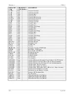
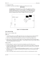
K1
K2
U18
U33
16305-1-#
Serial #
U38
U36
U37
Firmware
EPROMs
MG
0014
50
Figure 10-5 I/O Expander Board
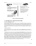
10.5.5 Ethernet Cable
Figure 10-6 shows the Ethernet cable.
REMOVAL
1.
At the Ethernet connection on the MPU Controller board, press the locking tab on the cable-mounted RJ-45
connector toward the circuit board and withdraw the connector from the board-mounted connector.
2.
Remove the Controller board and I/O Expander board, if present, as described in preceding sections.
3.
Inside the case, at the rear panel, press the locking tab on the cable-mounted connector upward and withdraw
the connector from the rear panel mounted connector. A long flat-blade screwdriver may be needed to press the
locking tab upward and release the connector.
INSTALLATION
1.
Referring to Figure 10-6, perform the steps under Case Connection to install the cable in the case.
2.
Install the I/O Expander board as described in a preceding section. Partially install the MPU Controller board;
the Ethernet connector should be accessible. The Ethernet cable must lie on the floor of the case, between the
Expander and Controller boards.
3.
In Figure 10-6, refer to the steps under MPU Controller Board Connection to mate the free end of the Ethernet
cable with the connector on the MPU Controller board. Dress the cable so that it will not interfere with the
Display Assembly.
4.
Fully install the MPU Controller board and reassemble the controller as described in preceding sections.
Содержание 353
Страница 12: ...Contents UM353 1B x April 2012 ...
Страница 22: ...Introduction UM353 1B April 2012 1 10 ...
Страница 30: ...Configuration Overview UM353 1B April 2012 2 8 ...
Страница 122: ...Function Blocks UM353 1B April 2012 3 92 ...
Страница 168: ...Data Mapping UM353 1B April 2012 6 28 ...
Страница 204: ...Controller and System Test UM353 1B April 2012 9 8 ...
Страница 222: ...Calibration UM353 1B April 2012 11 4 ...
Страница 226: ...Circuit Description UM353 1B April 2012 12 4 ...
Страница 238: ...Model Designation and Specifications UM353 1B April 2012 13 12 EC Declaration of Conformity ...
Страница 239: ...UM353 1B Model Designation and Specifications April 2012 13 13 Annex A to the EC Declaration of Conformity ...
Страница 240: ...Model Designation and Specifications UM353 1B April 2012 13 14 ...
Страница 244: ...Abbreviations And Acronyms UM353 1B 14 4 April 2012 ...