


Maintenance
UM353-1
April
2012
10-10
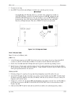
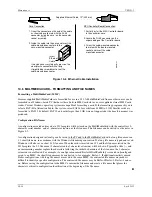
To replace the fuse:
1.
Refer to Section 10.5.2 and remove the Display Assembly
2.
Refer to Section 10.5.3 and remove the MPU Controller board.
3.
While the controller is apart, visually inspect the assemblies for overheated or otherwise damaged components.
4.
Remove the failed fuse and read the fuse ratings. Install a replacement fuse.
•
120/240 Vac MPU Controller board – A 0.5A fuse may be replaced with a 0.4A or 0.5A, 250V, SloBlo
fuse. A 0.4A fuse must be replaced with a 0.4A, 250V, SloBlo fuse.
•
24 Vdc MPU Controller board – Install a 2A, 250V, SloBlo fuse.
5.
Reassemble the controller. Refer to the above referenced sections as necessary.
6.
Apply power to the controller. Operate the controller off-line for several minutes to be sure that a condition
does not exist that will cause the replacement fuse to fail.
10.5.2 Display Assembly
To replace a Display Assembly, see Section 10.5.2.1. To replace the bezel or the circuit board, perform the
procedures in Sections 10.5.2.1 and 10.5.2.2.
10.5.2.1 To Replace a Display Assembly
REMOVAL:
1.
In a hazardous area, remove power from the Controller.
2.
Protect the station’s electronic components from electrostatic discharge. Fasten a conductive wrist
strap around your wrist and ground the strap to the ground screw on the Controller’s case, an
unpainted area on the panel, or a grounded static dissipative work mat.
3.
Loosen the Display Assembly’s two faceplate screws. One is above the numeric display and one behind the
flip-down door at the bottom of the faceplate.
4.
Pull the Assembly from the panel about 1.5" (38 mm).
5.
Look behind the Assembly and locate the display cable from the MPU Controller board. Open the connector
locking levers on the Assembly mounted connector to eject the cable mounted connector.
6.
Place the Display Assembly in a static shielding bag and set it aside.
7.
Go to the following sections to remove a circuit board or replace the power input fuse.
INSTALLATION
1.
Hold the Display Assembly close to the open case and mate the display cable with the connector on the Display
Assembly circuit board. Check that the locking levers on the connector fully engaged the cable mounted
connector. The cable is keyed.
2.
Align the Display Assembly with the case. To ensure water tightness, use a torque screwdriver set to 6 inch-
pounds to tighten the two faceplate screws. Alternatively, use a screwdriver to tighten the screws until a
slight
resistance
is felt, then tighten an additional ½ turn. DO NOT OVERTIGHTEN.
3.
Remove the wrist strap.
NOTE
When changing a Display Assembly with the controller powered-up and an error code
present, the displays will light in a random pattern except for the alphanumeric display
which will show the error code. Clear the error to clear the displays.
Содержание 353
Страница 12: ...Contents UM353 1B x April 2012 ...
Страница 22: ...Introduction UM353 1B April 2012 1 10 ...
Страница 30: ...Configuration Overview UM353 1B April 2012 2 8 ...
Страница 122: ...Function Blocks UM353 1B April 2012 3 92 ...
Страница 168: ...Data Mapping UM353 1B April 2012 6 28 ...
Страница 204: ...Controller and System Test UM353 1B April 2012 9 8 ...
Страница 222: ...Calibration UM353 1B April 2012 11 4 ...
Страница 226: ...Circuit Description UM353 1B April 2012 12 4 ...
Страница 238: ...Model Designation and Specifications UM353 1B April 2012 13 12 EC Declaration of Conformity ...
Страница 239: ...UM353 1B Model Designation and Specifications April 2012 13 13 Annex A to the EC Declaration of Conformity ...
Страница 240: ...Model Designation and Specifications UM353 1B April 2012 13 14 ...
Страница 244: ...Abbreviations And Acronyms UM353 1B 14 4 April 2012 ...