Data Mapping
UM353-1B
April
2012
6-18
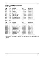
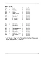
Analog Indicator [ODA]
Code
R/W
Description
Range
Coil(MB)
L#P1AA
R
1-Process 1 Alarm A is Active
1/0
00296+48(#-1)
L#P1AN
R/W
1-Process 1 Alarm A is Not Acknowledged
1/0
00297+48(#-1)
L#P1AE
R/W
1-Process 1 Alarm A is Enabled
1/0
00298+48(#-1)
L#P1BA
R
1-Process 1 Alarm B is Active
1/0
00299+48(#-1)
L#P1BN
R/W
1-Process 1 Alarm B is Not Acknowledged
1/0
00300+48(#-1)
L#P1BE
R/W
1-Process 1 Alarm B is Enabled
1/0
00301+48(#-1)
L#P2AA
R
1-Process 2 Alarm A is Active
1/0
00302+48(#-1)
L#P2AN
R/W
1-Process 2 Alarm A is Not Acknowledged
1/0
00303+48(#-1)
L#P2AE
R/W
1-Process 2 Alarm A is Enabled
1/0
00304+48(#-1)
L#P2BA
R
1-Process 2 Alarm B is Active
1/0
00305+48(#-1)
L#P2BN
R/W
1-Process 2 Alarm B is Not Acknowledged
1/0
00306+48(#-1)
L#P2BE
R/W
1-Process 2 Alarm B is Enabled
1/0
00307+48(#-1)
L#OS1
R/W
1-Alarms - Out of Service
1/0
00308+48(#-1)
L#PB1
R/W
PB1SW Input MD (*)
1/0
00309+48(#-1)
L#PB2
R/W
PB2SW Input MD (*)
1/0
00310+48(#-1)
L#PB3
R/W
PB3SW Input MD (*)
1/0
00311+48(#-1)
L#P3AA
R
1-Process 3 Alarm A is Active
1/0
00312+48(#-1)
L#P3AN
R/W
1-Process 3 Alarm A is Not Acknowledged
1/0
00313+48(#-1)
L#P3AE
R/W
1-Process 3 Alarm A is Enabled
1/0
00314+48(#-1)
L#P3BA
R
1-Process 3 Alarm B is Active
1/0
00315+48(#-1)
L#P3BN
R/W
1-Process 3 Alarm B is Not Acknowledged
1/0
00316+48(#-1)
L#P3BE
R/W
1-Process 3 Alarm B is Enabled
1/0
00317+48(#-1)
L#P4AA
R
1-Process 4 Alarm A is Active
1/0
00318+48(#-1)
L#P4AN
R/W
1-Process 4 Alarm A is Not Acknowledged
1/0
00319+48(#-1)
L#P4AE
R/W
1-Process 4 Alarm A is Enabled
1/0
00320+48(#-1)
L#P4BA
R
1-Process 4 Alarm B is Active
1/0
00321+48(#-1)
L#P4BN
R/W
1-Process 4 Alarm B is Not Acknowledged
1/0
00322+48(#-1)
L#P4BE
R/W
1-Process 4 Alarm B is Enabled
1/0
00323+48(#-1)
L#OS
R/W
1-Alarms - Out of Service
1/0
00324+48(#-1)
L#CC
R
1-Configuration has Changed
1/0
00325+48(#-1)
L#NA
R/W
1-Unacknowledged Loop Event
1/0
00326+48(#-1)
L#AE
R
1-Active Loop Event
1/0
00327+48(#-1)
* These bits indicate the status of the switch input MD. A write of a “1” will have the same effect as pressing and
releasing the button on the faceplate. If the action of the switch is sustained the switch will change position. If
the action is momentary, the switch will close for one scan cycle.
Содержание 353
Страница 12: ...Contents UM353 1B x April 2012 ...
Страница 22: ...Introduction UM353 1B April 2012 1 10 ...
Страница 30: ...Configuration Overview UM353 1B April 2012 2 8 ...
Страница 122: ...Function Blocks UM353 1B April 2012 3 92 ...
Страница 168: ...Data Mapping UM353 1B April 2012 6 28 ...
Страница 204: ...Controller and System Test UM353 1B April 2012 9 8 ...
Страница 222: ...Calibration UM353 1B April 2012 11 4 ...
Страница 226: ...Circuit Description UM353 1B April 2012 12 4 ...
Страница 238: ...Model Designation and Specifications UM353 1B April 2012 13 12 EC Declaration of Conformity ...
Страница 239: ...UM353 1B Model Designation and Specifications April 2012 13 13 Annex A to the EC Declaration of Conformity ...
Страница 240: ...Model Designation and Specifications UM353 1B April 2012 13 14 ...
Страница 244: ...Abbreviations And Acronyms UM353 1B 14 4 April 2012 ...

