Calibration
UM353-1B
April
2012
11-2
11.1 ANALOG INPUT (AIN1-4)
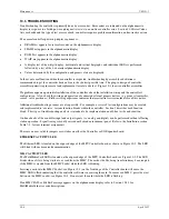
Analog input function blocks have been factory calibrated for 1 to 5 Vdc inputs. Recalibration should not be
required unless calibration parameters are to be changed. Periodic recalibration should not be necessary. To
calibrate an analog input, use the following procedure.
1.
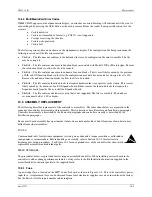
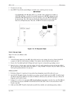
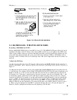
At the controller’s rear terminals, connect an electronic calibrator or precision reference source capable of
supplying a voltage between 0.000 and 5.000 Vdc to the selected analog input terminals (e.g. AIN1 or AIN2).
Refer to Section 7 Installation for terminal numbers and wiring guidelines. Ensure that terminal screws are
tight.
2.
If security is enabled, a level 1 or level 4 security combination will be needed to store the results of a
calibration. Refer to SECUR-Security in Section 3.1.2 for additional information.
3.
Apply power to the station.
4.
Press the ENTER CONF button to enter the configuration mode at the MENU level. Rotate the Pulser Knob to
select ‘STATION’ on the alphanumeric (lower) display.
5.
Press the STEP DOWN button to choose options at the station level and rotate the Pulser Knob to select ‘CAL’
on the alphanumeric display.
6.
Press the STEP DOWN button to enter the FUNCTION BLOCK level. Rotate the Pulser Knob to select the
desired input (e.g. AIN1 or AIN2).
7.
Press the STEP DOWN button to enter the PARAMETER level.
8.
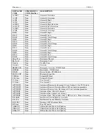
Rotate the Pulser Knob to select the desired parameter, CAL ZERO, shown on the alphanumeric display.
9.
Press the STEP DOWN button to enter the VALUE level (‘CAL’ appears on upper display).
10.
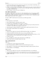
Set the precision voltage source to the zero input value (0.000 to 1.000 Vdc).
11.
Press STORE to lock-in the desired value. If ENTER COM appears in the alphanumeric display, security is
enabled and steps 1) through 5) must be performed to store the calibration. Otherwise, go to step 14.
1)
The numeric display shows 000000 with the right-most digit flashing. Rotate the pulser knob to set the
units digit to the correct number.
2)
Press the TAG/
Å
key to select the next digit, the tens digit. Rotate the pulser knob to select a number for
that digit.
3)
Move to and select the needed number for each remaining digit.
4)
Press ENTER. If the combination entered is incorrect, “ACCESS/DENIED” will be displayed and the
controller will return to the parameter level. Otherwise, go to step 14.
12.
Press the STEP UP button. Rotate the Pulser Knob to select the ‘CAL FULL’ parameter.
13.
Press the STEP DOWN button to enter the VALUE level (‘CAL’ appears on upper display).
14.
Set the voltage source to the full scale input value (4.000 to 5.000 Vdc).
15.
Press STORE.
16.
For verification perform the following steps:
1)
Press STEP UP button. Rotate Pulser Knob to select ‘CAL VIEW’ parameter.
2)
Press STEP DOWN button to enter VALUE level. Set precision voltage source to zero input voltage. The
display should read the real number at the block output.
3)
Set source to full scale voltage. The display should read the real number at the block output.
17.
If all points have been calibrated and verified, press EXIT button to leave the calibration mode and enter the
operation mode. If additional function blocks are to be calibrated and verified, press the STEP UP button to
enter the FUNCTION BLOCK level. Perform steps 2 -19 for each function block.
Содержание 353
Страница 12: ...Contents UM353 1B x April 2012 ...
Страница 22: ...Introduction UM353 1B April 2012 1 10 ...
Страница 30: ...Configuration Overview UM353 1B April 2012 2 8 ...
Страница 122: ...Function Blocks UM353 1B April 2012 3 92 ...
Страница 168: ...Data Mapping UM353 1B April 2012 6 28 ...
Страница 204: ...Controller and System Test UM353 1B April 2012 9 8 ...
Страница 222: ...Calibration UM353 1B April 2012 11 4 ...
Страница 226: ...Circuit Description UM353 1B April 2012 12 4 ...
Страница 238: ...Model Designation and Specifications UM353 1B April 2012 13 12 EC Declaration of Conformity ...
Страница 239: ...UM353 1B Model Designation and Specifications April 2012 13 13 Annex A to the EC Declaration of Conformity ...
Страница 240: ...Model Designation and Specifications UM353 1B April 2012 13 14 ...
Страница 244: ...Abbreviations And Acronyms UM353 1B 14 4 April 2012 ...


