Function Blocks
UM353-1B
April
2012
3-52
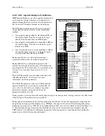
3.2.54 ODA - Operator Display for Analog Indication & Alarming
ODA blocks are one of five operator displays that are used on a one
per loop basis to configure the local operator display functions and
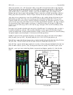
network parameters. See the i|ware PC faceplate on the next page.
The block will display up to four process variables P1 to P4 in both
analog bargraph and digital form. Two alarms are associated with
each process variable. They can be configured as HI or LO alarms.
Each alarm function has associated block outputs that are high (1)
when the alarm is active. Output LE is high (1) when a loop event is
active. Output SE is high when a station error is active. LOOP #
parameters are used to index reads and writes to Modbus network
parameters. See Section 5 for network parameters.
The VIEW OD parameter, when set to YES, enables the operator
display to be viewed and accessed locally. In cases where it is desired
to view display or operation parameters only from a network
workstation, the parameter should be set to NO.
Range pointers (i.e. R1 to R4) for all four process inputs must be
configured to define the range of each variable input (i.e. P1 to P4). If
these parameters are not configured, the bargraphs will be scaled using
the engineering range of 0.00 to 100.00. This information also defines
the scaling of the loop information provided to a remote workstation
over the network (i.e. Modbus or Modbus/TCP Ethernet).
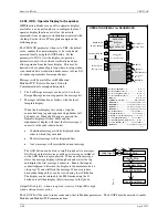
Each process variable can be displayed on the local faceplate using the
D button. When first stepping into a loop using the Loop button, the
loop tag will be displayed (e.g. AnDisp1). However, if there is a point
within the loop that has an unacknowledged alarm, that point will be
displayed alternating between the point tag and the alarm condition
(e.g. PI693/3B LO). Press the D button to scroll through the analog
points displaying the point tag (e.g. TI712) in the alphanumeric and
the value of the point in the digital display (e.g. 348.47). Press the
UNITS button to display the units of the point. Press the Loop tag to
return to displaying the loop tag.
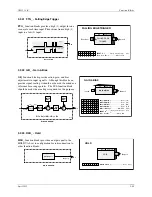
Alarm Types
HI
compares the process input with the limit setting and trips the
alarm status high (1) when the process is equal to or higher than the
limit setting. The alarm status will clear (0) when the process is less
than the limit setting minus the deadband.
LO
compares the process input with the limit setting and trips the
alarm status high (1) when the process is equal to or less than the limit
setting. The alarm status will clear (0) when the process is greater than
the limit setting plus the deadband.
OR
compares the process input with the range limits referenced by the
range pointer parameter. It will trip the alarm status high (1) when the
process is equal to or greater than the high limit, or equal to or less
than the low limit. The alarm status will clear (0) when the process is
less than the high limit minus the deadband or greater than the low
limit plus the deadband.
P
rocess
1
Operator Display for Analog indication & alarming
B1
ODA
P1
R2
R3
Alarm
B
P
1
INPUT P4
(H)
.........................
loop tag.block tag.output (null)
INPUT P3
(H)
.........................
loop tag.block tag.output (null)
INPUT P2
(H)
.........................
loop tag.block tag.output (null)
INPUT P1
(H)
.........................
loop tag.block tag.output (null)
R4
LE
L
oop
E
vent
A1
P
rocess
1 - R
an
G
e
P
oin
T
e
R
(S)
.........
loop tag.block tag (null)
P
G
R
P T R
G
R
P T R
P
I N P U T
I
I
I
N
N
N
P
P
P
U
U
U
T
T
T
P
P
G
R
P T R
P
G
R
P T R
Operator Display
for
Analog Indication
&
Alarming
WD
W
atch
D
og
P2
Process
R
ange
1
R1
P3
P4
O D
W
I E
V
VIEW
O
perator
D
isplay
(H)
......................... NO/YES
(YES)
SE
S
tation
E
rror
Process
R
ange
2
P
rocess
2
Process
R
ange
3
P
rocess
3
Process
R
ange
4
P
rocess
4
1
2
3
4
1
P 2
P 3
P 4
P
rocess
2 - R
an
G
e
P
oin
T
e
R
(S)
.........
loop tag.block tag (null)
P
rocess
3 - R
an
G
e
P
oin
T
e
R
(S)
.........
loop tag.block tag (null)
P
rocess
4 - R
an
G
e
P
oin
T
e
R
(S)
.........
loop tag.block tag (null)
1 A
L I M I T
1 B
L I M I T
Process
1
Alarm
A LIMIT
(S)
............................. Real
(110.0)
Process
1
Alarm
B LIMIT
(S)
............................. Real
(-10.0)
2 A
L I M I T
2 B
L I M I T
Process
2
Alarm
A
LIMIT
(S)
............................. Real
(110.0)
Process
2
Alarm
B LIMIT
(S)
............................. Real
(-10.0)
3 A
L I M I T
3 B
L I M I T
Process
3
Alarm
A LIMIT
(S)
............................. Real
(110.0)
Process
3
Alarm
B LIMIT
(S)
............................. Real
(-10.0)
4 A
L I M I T
4 B
L I M I T
Process
4
Alarm
A LIMIT
(S)
............................. Real
(110.0)
Process
4
Alarm
B LIMIT
(S)
............................. Real
(-10.0)
1 A
D B A N D
Process
1
Alarm
A D
ead
BAND
(S)
.....
0.1/0.5/1.0/5.0% (0.5)
1 B
D B A N D
Process
1
Alarm
B D
ead
BAND
(S)
.....
0.1/0.5/1.0/5.0%
(0.5)
2 A
D B A N D
Process
2
Alarm
A D
ead
BAND
(S)
.....
0.1/0.5/1.0/5.0%
(0.5)
2 B
D B A N D
Process
2
Alarm
B D
ead
BAND
(S)
.....
0.1/0.5/1.0/5.0%
(0.5)
3 A
D B A N D
Process
3
Alarm
A D
ead
BAND
(S)
.....
0.1/0.5/1.0/5.0%
(0.5)
3 B
D B A N D
Process
3
Alarm
B D
ead
BAND
(S)
.....
0.1/0.5/1.0/5.0%
(0.5)
4 A
D B A N D
Process
4
Alarm
A D
ead
BAND
(S)
.....
0.1/0.5/1.0/5.0%
(0.5)
4 A
D B A N D
Process
4
Alarm
B D
ead
BAND
(S)
.....
0.1/0.5/1.0/5.0%
(0.5)
1 A
P U
E N
Process
1
Alarm
A P
ower
U
p
EN
abled
(S)
.NO/YES
(YES)
1 B
P U
E N
Process
1
Alarm
B P
ower
U
p
EN
abled
(S)
.NO/YES
(YES)
2 A
P U
E N
Process
2
Alarm
A P
ower
U
p
EN
abled
(S)
.NO/YES
(YES)
2 B
P U
E N
Process
2
Alarm
B P
ower
U
p
EN
abled
(S)
.NO/YES
(YES)
3 A
P U
E N
Process
3
Alarm
A P
ower
U
p
EN
abled
(S)
.NO/YES
(YES)
3 B
P U
E N
Process
3
Alarm
B P
ower
U
p
EN
abled
(S)
.NO/YES
(YES)
4 A
P U
E N
Process
4
Alarm
A P
ower
U
p
EN
abled
(S)
.NO/YES
(YES)
4 B
P U
E N
Process
4
Alarm
B P
ower
U
p
EN
abled
(S)
.NO/YES
(YES)
1 A
P R
O R
Process
1
Alarm
A PRIOR
ity
(S)
................1/2/3/4/5
(3)
I
1 B
P R
O R
Process
1
Alarm
B PRIOR
ity
(S)
................1/2/3/4/5
(3)
I
2 A
P R
O R
Process
2
Alarm
A PRIOR
ity
(S)
................1/2/3/4/5
(3)
I
2 B
P R
O R
Process
2
Alarm
B PRIOR
ity
(S)
................1/2/3/4/5
(3)
I
3 A
P R
O R
Process
3
Alarm
A PRIOR
ity
(S)
................1/2/3/4/5
(3)
I
3 B
P R
O R
Process
3
Alarm
B PRIOR
ity
(S)
................1/2/3/4/5
(3)
I
4 A
P R
O R
Process
4
Alarm
A PRIOR
ity
(S)
................1/2/3/4/5
(3)
I
4 B
P R
O R
Process
4
Alarm
B PRIOR
ity
(S)
................1/2/3/4/5
(3)
I
1 A
T
P E
Process
1
Alarm
A TYPE
(S)
.............none/HI/LO/or
(HI)
Y
1 B
T
P E
Process
1
Alarm
B TYPE
(S)
.............none/HI/LO/or
(LO)
Y
2 A
T
P E
Process
2
Alarm
A TYPE
(S)
.............none/HI/LO/or
(HI)
Y
2 B
T
P E
Process
2
Alarm
B TYPE
(S)
.............none/HI/LO/or
(LO)
Y
3 A
T
P E
Process
3
Alarm
A TYPE
(S)
.............none/HI/LO/or
(HI)
Y
3 B
T
P E
Process
3
Alarm
B TYPE
(S)
.............none/HI/LO/or
(LO)
Y
4 A
T
P E
Process
4
Alarm
A TYPE
(S)
.............none/HI/LO/or
(HI)
Y
4 B
T
P E
Process
4
Alarm
B TYPE
(S)
.............none/HI/LO/or
(LO)
Y
1 A
D
I N
Proc
1
Alarm
A DeLay IN
(S)
..... 0/.4/1/2/5/15/30/60
(0)
L
1 B
D
I N
Proc
1
Alarm
B DeLay IN
(S)
..... 0/.4/1/2/5/15/30/60
(0)
L
2 A
D
I N
Proc
2
Alarm
A DeLay IN
(S)
..... 0/.4/1/2/5/15/30/60
(0)
L
2 B
D
I N
Proc
2
Alarm
B DeLay IN
(S)
..... 0/.4/1/2/5/15/30/60
(0)
L
3 A
D
I N
Proc
3
Alarm
A DeLay IN
(S)
..... 0/.4/1/2/5/15/30/60
(0)
L
3 B
D
I N
Proc
3
Alarm
B DeLay IN
(S)
..... 0/.4/1/2/5/15/30/60
(0)
L
4 A
D
I N
Proc
4
Alarm
A DeLay IN
(S)
..... 0/.4/1/2/5/15/30/60
(0)
L
4 B
D
I N
Proc
4
Alarm
B DeLay IN
(S)
..... 0/.4/1/2/5/15/30/60
(0)
L
1 A
D
O
T
Proc
1
Alarm
A DeLay OUT
(S)
. 0/.4/1/2/5/15/30/60
(0)
L
U
1 B
D
O
T
Proc
1
Alarm
B DeLay OUT
(S)
. 0/.4/1/2/5/15/30/60
(0)
L
U
2 A
D
O
T
Proc
2
Alarm
A DeLay OUT
(S)
. 0/.4/1/2/5/15/30/60
(0)
L
U
2 B
D
O
T
Proc
2
Alarm
B DeLay OUT
(S)
. 0/.4/1/2/5/15/30/60
(0)
L
U
3 A
D
O
T
Proc
3
Alarm
A DeLay OUT
(S)
. 0/.4/1/2/5/15/30/60
(0)
L
U
3 B
D
O
T
Proc
3
Alarm
B DeLay OUT
(S)
. 0/.4/1/2/5/15/30/60
(0)
L
U
4 A
D
O
T
Proc
4
Alarm
A DeLay OUT
(S)
. 0/.4/1/2/5/15/30/60
(0)
L
U
4 B
D
O
T
Proc
4
Alarm
B DeLay OUT
(S)
. 0/.4/1/2/5/15/30/60
(0)
L
U
1 A
R
B
K
Process
1
Alarm
A R
in
G B
a
CK
(S)
............ NO/YES
(NO)
G
C
1 B
R
B
K
Process
1
Alarm
B R
in
G B
a
CK
(S)
............ NO/YES
(NO)
G
C
2 A
R
B
K
Process
2
Alarm
A R
in
G B
a
CK
(S)
............ NO/YES
(NO)
G
C
2 B
R
B
K
Process
2
Alarm
B R
in
G B
a
CK
(S)
............ NO/YES
(NO)
G
C
3 A
R
B
K
Process
3
Alarm
A R
in
G B
a
CK
(S)
............ NO/YES
(NO)
G
C
3 B
R
B
K
Process
3
Alarm
B R
in
G B
a
CK
(S)
............ NO/YES
(NO)
G
C
4 A
R
B
K
Process
4
Alarm
A R
in
G B
a
CK
(S)
............ NO/YES
(NO)
G
C
4 B
R
B
K
Process
4
Alarm
B R
in
G B
a
CK
(S)
............ NO/YES
(NO)
G
C
Alarm
A
P
1
B3
Alarm
B
P
3
A3
Alarm
A
P
3
B4
Alarm
B
P
4
A4
Alarm
A
P
4
B2
Alarm
B
P
2
A2
Alarm
A
P
2
P
P
P
P
1
2
3
4
T A G
T A G
T A G
T A G
P
rocess
1
TAG
(S)
................................8 ASCII Char
(P1 TAG)
P
rocess
2
TAG
(S)
................................8 ASCII Char
(P2 TAG)
P
rocess
3
TAG
(S)
................................8 ASCII Char
(P3 TAG)
P
rocess
4
TAG
(S)
................................8 ASCII Char
(P4 TAG)
.
Rev. 3
L
O P
#
O
LOOP #
(S)
................................................. 01 to 25
(null)
Содержание 353
Страница 12: ...Contents UM353 1B x April 2012 ...
Страница 22: ...Introduction UM353 1B April 2012 1 10 ...
Страница 30: ...Configuration Overview UM353 1B April 2012 2 8 ...
Страница 122: ...Function Blocks UM353 1B April 2012 3 92 ...
Страница 168: ...Data Mapping UM353 1B April 2012 6 28 ...
Страница 204: ...Controller and System Test UM353 1B April 2012 9 8 ...
Страница 222: ...Calibration UM353 1B April 2012 11 4 ...
Страница 226: ...Circuit Description UM353 1B April 2012 12 4 ...
Страница 238: ...Model Designation and Specifications UM353 1B April 2012 13 12 EC Declaration of Conformity ...
Страница 239: ...UM353 1B Model Designation and Specifications April 2012 13 13 Annex A to the EC Declaration of Conformity ...
Страница 240: ...Model Designation and Specifications UM353 1B April 2012 13 14 ...
Страница 244: ...Abbreviations And Acronyms UM353 1B 14 4 April 2012 ...


