UM353-1B
Maintenance
April 2012
10-9
10.4.3 MultiMediaCard Error Codes
If MMC FAIL appears on the alphanumeric display, an error has occurred. Flashing will continue until the event is
acknowledged by pressing the ACK button or the card is removed from the socket. Some possible reasons for the
error are:
•
Card is defective
•
Card is not formatted or format (e.g. FAT32) is not supported
•
Corrupt or missing file structure
•
Card is write-protected
•
Card is full
The following error codes can be shown on the alphanumeric display. The configuration file being read cannot be
further processed until the file error corrected.
•
FileErr1 – The file does not conform to the defined structure of a configuration file and is unusable. The file
may be corrupted.
•
FileErr2 – The file contains one or more function blocks associated with Model 353R or Procidia i|pac. Remove
those function blocks to allow the file to be loaded.
•
FileErr3 – The file contains one or more unknown function blocks. This is most likely caused by the presence
of LIL or LON function blocks in the file (the configuration may have been created for a design level A 353).
Remove the unknown function blocks to allow the file to be loaded.
•
FileErr4 – The file contains function blocks that require hardware that is not present in the station. This is most
likely caused by the absence of an I/O Expander board. Either remove the function blocks that require the
Expander board from the file or install the Expander board.
•
FileErr5 – The file contains a database revision that is not supported. The file is not usable. The database
revision must be Rev 4.00 or higher.
10.5 ASSEMBLY REPLACEMENT
The following describes replacement of the controller’s assemblies. The subsections below are organized in the
sequence of controller disassembly and reassembly. Most subsections have Removal and Installation paragraphs.
Controller disassembly is described by the Removal paragraphs and controller assembly is described by the
Installation paragraphs.
Each circuit board assembly has a part number label and a serial number label. Label locations shown herein may
differ from actual assemblies.
TOOLS:
Common hand tools for electronic equipment servicing are needed and a torque screwdriver, calibrated in
inch-pounds, is recommended. Before handling an assembly, refer to Section 10.2.4 for electrostatic
discharge prevention procedures. See Figure 10-1 for an exploded view of the controller that shows field
replaceable assemblies and individual parts.
FIELD UPGRADES:
The procedures below are provided for servicing an assembled controller. When installing a circuit board in the
controller to add or change performance features, always refer to the Kit Installation Instruction supplied in the
circuit board kit for details specific to the supplied board.
10.5.1 Fuse
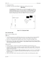
A power input fuse is located on the MPU Controller board as shown in Figure 10-2. This is the controller’s power
input fuse. A replacement fuse can be obtained from a local electronics supplier or can be ordered from the factory.
See the Parts List for fuse part number and description.
Содержание 353
Страница 12: ...Contents UM353 1B x April 2012 ...
Страница 22: ...Introduction UM353 1B April 2012 1 10 ...
Страница 30: ...Configuration Overview UM353 1B April 2012 2 8 ...
Страница 122: ...Function Blocks UM353 1B April 2012 3 92 ...
Страница 168: ...Data Mapping UM353 1B April 2012 6 28 ...
Страница 204: ...Controller and System Test UM353 1B April 2012 9 8 ...
Страница 222: ...Calibration UM353 1B April 2012 11 4 ...
Страница 226: ...Circuit Description UM353 1B April 2012 12 4 ...
Страница 238: ...Model Designation and Specifications UM353 1B April 2012 13 12 EC Declaration of Conformity ...
Страница 239: ...UM353 1B Model Designation and Specifications April 2012 13 13 Annex A to the EC Declaration of Conformity ...
Страница 240: ...Model Designation and Specifications UM353 1B April 2012 13 14 ...
Страница 244: ...Abbreviations And Acronyms UM353 1B 14 4 April 2012 ...


