


Maintenance
UM353-1
April
2012
10-4
10.3 TROUBLESHOOTING
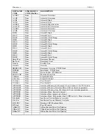
Troubleshooting the controller is primarily done by error codes. Error codes are indicated on the alphanumeric
display in response to a failed power-up diagnostic test or to an on-line controller error. Section 10.4 Error Codes
lists each code and the type of test or error check, controller response, problem confirmation, and corrective action.
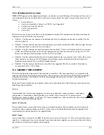
The normal controller power-up display sequence is:
•
DRAMTest appears for several seconds on the alphanumeric display
•
SRAMTest appears in the alphanumeric display
•
ROM Test appears in the alphanumeric display
•
WAIT may appear in the alphanumeric display
•
A display test of the 6-digit display, horizontal and vertical bargraphs, and individual LEDs is performed
followed by a test of the 8-character alphanumeric display
•
Values determined by the configuration and process state are displayed
In the event a malfunction within the controller is suspected, troubleshooting by assembly substitution is
recommended to get the controller back on-line in the shortest possible time. The plug-in design of controller
assemblies permits rapid removal and replacement to isolate a defect. Figure 10-1 shows controller assemblies.
If a problem appears upon initial installation of the controller, check the installation wiring and the controller’s
configuration. Also, check the wiring and operation of connected external process devices (e.g. process transmitter,
sensor, valve positioner). Field servicing experience indicates that most initial service incidents are of this nature.
Additional troubleshooting avenues are also possible. For example, a series of test configurations may be created
and implemented to ‘exercise’ various function blocks within the controller. Section 3 describes each function
block. This type of troubleshooting analysis is intended to be implemented in an off-line test bench situation.
On-line checks of the controller input and output signals (i.e. analog and digital) can be performed without affecting
station operation. Signal tracing is usually carried out behind an instrument panel. Refer to the Installation section,
Table 7-1, for rear terminal assignments.
There are no user settable jumpers or switches on either the Controller or I/O Expander board.
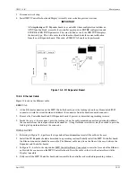
ETHERNET ACTIVITY LED
The Ethernet LED is located on the exposed edge of the MPU Controller board, as shown in Figure 10-2. The LED
will blink with each received communication.
MMC ACTIVITY LED
The MultiMediaCard LED is located on the exposed edge of the MPU Controller board, see Figure 10-2. The LED
blinks when a file is being written to or read from the MMC. The card or the file being transferred may be corrupted
if the MMC is ejected from the MMC Socket while the LED is blinking.
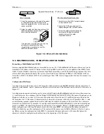
Inserting a card into the MMC Socket (see Figure 10-3) on the front edge of the Controller board will cause the
MMC LED to flash indicating that the controller software is accessing the card. To remove an MMC, press the eject
button on the MMC socket; see Figure 10-3. Do not eject the card while the LED is flashing.
If an MMC FAIL or FileErr# message appears on the alphanumeric display, refer to Section 10.4.3 for
MultiMediaCard error code descriptions.
Содержание 353
Страница 12: ...Contents UM353 1B x April 2012 ...
Страница 22: ...Introduction UM353 1B April 2012 1 10 ...
Страница 30: ...Configuration Overview UM353 1B April 2012 2 8 ...
Страница 122: ...Function Blocks UM353 1B April 2012 3 92 ...
Страница 168: ...Data Mapping UM353 1B April 2012 6 28 ...
Страница 204: ...Controller and System Test UM353 1B April 2012 9 8 ...
Страница 222: ...Calibration UM353 1B April 2012 11 4 ...
Страница 226: ...Circuit Description UM353 1B April 2012 12 4 ...
Страница 238: ...Model Designation and Specifications UM353 1B April 2012 13 12 EC Declaration of Conformity ...
Страница 239: ...UM353 1B Model Designation and Specifications April 2012 13 13 Annex A to the EC Declaration of Conformity ...
Страница 240: ...Model Designation and Specifications UM353 1B April 2012 13 14 ...
Страница 244: ...Abbreviations And Acronyms UM353 1B 14 4 April 2012 ...