Model Designation and Specifications
UM353-1B
April
2012
13-4
SERVICE PART DESCRIPTION PART
NO.
- ELECTRONIC ASSEMBLIES AND RELATED PARTS -
Display Assembly Kit, for Model 353 _ _ F _ _ _ _ _
16353-53*
Display Assembly Bezel Replacement Kit
Contains gray bezel, keypad, pulsar knob, and installation instruction
Does not contain Display Board or black Display Assembly mounting screws
16353-163
MPU Controller Board Kit for 120/240 Vac Power Input, for
Model 353A _ _ _ _ _ _ _
TGX:16353-
302*
MPU Controller Board Kit for 24 Vdc Power Input, for
Model 353D _ _ _ _ _ _ _
TGX:16353-
303*
I/O Expander Board Kit, for Model 353 _ _ _ 1 _ _ _ _. Contains I/O Expander
Board and Range Resistor and Reference Junction Kit. Does not include terminals
27-52; Case supplied with all needed connectors.
16353-52*
Spare Parts Kit, includes:
Power Input and Range Resistor Kit, includes:
250 Ohm, 0.1%, 3W, WW resistor and insulating sleeving, qty 3 each
Crimp-on connector, qty 6
Range Resistor and Reference Junction Kit, includes:
250 Ohm, 0.1%, 3W, WW resistor, qty 1
3.75 Ohm, 1%, 3W, WW resistor, qty 2
Insulating sleeving, qty 5
Crimp-on connector, qty 6
100 Ohm reference junction for TC inputs, qty 2
Crimp-on Connector, qty 18
O-Ring, Display Assembly, qty 1
Fuse, 120/240 Vac MPU Controller board: 0.4A or 0.5A, 250V, SloBlo, qty 1
Fuse, 24 Vdc MPU Controller board: 2A, 250V, SloBlo, qty 1
Case Mounting Clip and 8-32 x 1 Fillister Hd. Screw, qty 2 each
Case Ground Screw (Green), qty 1
16353-131*
- CASE AND CASE MOUNTED CONNECTORS -
Standard Case with Ethernet Connector and Case-Mounted Connectors, Case
Option 4 (Model 353_4...), includes:
Flange and Case Assembly, qty 1
Expanded Connector Socket Assembly with Ethernet Connector and 52
Case-Mounted Connectors and plug mating connectors
Connector Cover
Case Mounting Clip and 8-32 x 1 Fillister Hd. Screw, qty 2 each
Ground Screw, Green, qty 1
15353-206
Replacement Ethernet Cable Kit, for an Option 4 case.
15720-368
Notes to Kits:
•
Refer to User’s Manual UM353-1B for accessory part numbers and for servicing a controller.
•
See drawing(s) on previous page for disassembly and item reference numbers.
•
“*” Identifies a recommended on-hand spare part for the indicated model. Include nameplate information when ordering.
•
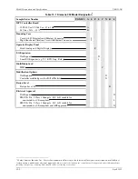
Sample model number: TGX:353 A 4 F 1 C N B 4
•
NS = Not Shown
Содержание 353
Страница 12: ...Contents UM353 1B x April 2012 ...
Страница 22: ...Introduction UM353 1B April 2012 1 10 ...
Страница 30: ...Configuration Overview UM353 1B April 2012 2 8 ...
Страница 122: ...Function Blocks UM353 1B April 2012 3 92 ...
Страница 168: ...Data Mapping UM353 1B April 2012 6 28 ...
Страница 204: ...Controller and System Test UM353 1B April 2012 9 8 ...
Страница 222: ...Calibration UM353 1B April 2012 11 4 ...
Страница 226: ...Circuit Description UM353 1B April 2012 12 4 ...
Страница 238: ...Model Designation and Specifications UM353 1B April 2012 13 12 EC Declaration of Conformity ...
Страница 239: ...UM353 1B Model Designation and Specifications April 2012 13 13 Annex A to the EC Declaration of Conformity ...
Страница 240: ...Model Designation and Specifications UM353 1B April 2012 13 14 ...
Страница 244: ...Abbreviations And Acronyms UM353 1B 14 4 April 2012 ...

