background image

14.1. CONFIGURATION

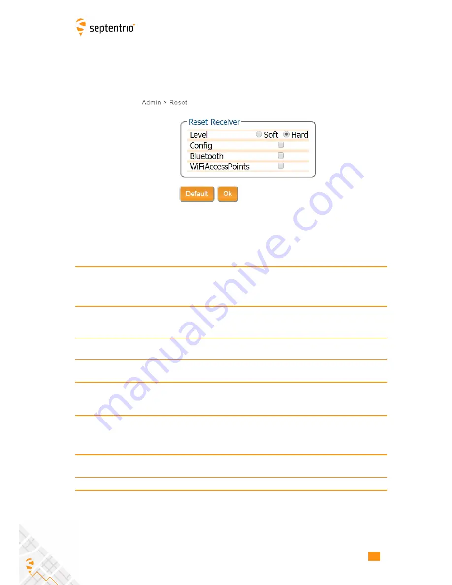
14.1.3 Reset

1. Click The

Admin

tab.

2. Select the Reset Option.

Figure 14-3:

Admin - Reset

3. Select the desired reset level using Table 8 and Table 9.

4. Click OK

5. The Altus NR2 restarts

Level

Description

Soft

This is a reset of the receiver’s firmware. The receiver will restart operating in

the same configuration as before the command was issued, unless the

‘Config’ option has been ticked.

Hard

This is similar to a power off/on sequence. After hardware reset, the receiver

will copy the Boot configuration into the Current configuration..

Upgrade

Set the receiver into upgrade mode. After a few seconds, the receiver is

ready to accept an upgrade file (SUF format) from any of its connections.

Table 14.1-3:

Altus NR2 Reset Levels

Erase

Description

Config

The RxDefault configuration is copied into the receiver’s Boot and Current

configurations. The User1 and User2 configurations remain unchanged.

Bluetooth

All information about previously paired devices is cleared.

Table 14.1-4:

Altus NR2 Reset- Memory Erase Options

73

Содержание Altus NR2

Страница 1: ...Altus NR2 User Manual ...

Страница 2: ...ts in this document is for informational purposes only and does not constitute an endorsement or a recommendation Septentrio NV assumes no responsibility with regard to the performance or use of the Altus NR2 due to GNSS characteristics USA Department of Defense operations control atmospheric effects multipath and RF interference All understandings agreements or warranties take place directly betw...

Страница 3: ...ents 14 3 Altus NR2 Overview 15 3 1 FRONT PANEL 15 3 1 1 Power Button Functions 16 3 2 LOCATION OF BATTERIES AND SIM CARD 17 3 3 CLOSING THE BATTERY DOOR 17 3 4 ALTUS NR2 CONNECTOR 18 3 5 THE WEB INTERFACE 19 4 Initial set up 20 4 1 PREREQUISITES 20 4 2 INSERT THE MICRO SIM CARD 21 4 3 INSERT THE BATTERIES 21 4 4 SWITCH ON THE ALTUS NR2 21 4 5 WAIT FOR THE ALTUS NR2 TO START UP 21 4 6 MAKE SURE TH...

Страница 4: ...TING THE ALTUS NR2 BASE STATION POSITION 42 11 Altus NR2 RTK Rover to Base configuration point to point 43 11 1 ALTUS NR2 RTK BASE ROVER CELLULAR CONNECTION 43 11 2 ALTUS NR2 RTK BASE ROVER WI FI CONNECTION 48 12 PinPoint GIS 54 12 1 INTRODUCTION 54 12 2 CREATING A MAP 56 12 3 CONNECTING TO THE INTERNET 58 12 4 USING PINPOINT GIS WEB 59 12 4 1 Optional Auto filling of GNSS attributes1 61 12 5 USING ...

Страница 5: ...S ICONS ON THE WEB INTERFACE 77 15 2 FRONT PANEL LEDS 78 15 3 THE BATTERIES 79 15 3 1 Batteries 79 15 3 2 Charging 79 15 4 CELL MODEM COMMANDS 79 15 5 GLOSSARY OF ARCGIS AND PINPOINT GIS TERMS 80 15 6 LIST OF TYPICAL GNSS RELATED ACRONYMS 81 5 ...

Страница 6: ...o see you through the working day and beyond The charger and batteries are non proprietary so it is easy and inexpensive to keep spares Use your existing phone or tablet The Altus NR2 can communicate with any device with a Wi Fi radio Simply connect to the Altus NR2 open your browser and your Altus NR2 is configured within minutes Esri ready The Altus NR2 has been designed specifically for ArcGIS On...

Страница 7: ... thanks to PinPoint GIS With Septentrio s open architecture philosophy you have the choice of using data collector software from MicroSurvey FIELDGenius or Carlson SurvCE 1 2 1 GNSS Key Features 132 Channels with L1 L2 L2C GPS GLONASS and SBAS RTK SBAS DGPS and Standalone positioning modes Navigation performance Horizontal Vertical Standalone 1 3 m 1 9 m SBAS WAAS EGNOS MSAS 0 6 m 0 8 m DGPS RTCM1...

Страница 8: ...e for one year from date of purchase The warranty does not cover Defects due to accidents abuse misuse negligence abnormal use or any other non recommended use Defects due to environmental conditions that do not conform to Altus NR2 specifications Defects due to improper installation or operating procedures Defects due to modifications alterations or changes not made in accordance with the Altus NR2...

Страница 9: ...trio com support septentrio com septentrio_support Europe Septentrio NV Phone 32 16 300 800 Greenhill Campus Fax 32 16 221 640 Interleuvenlaan 15G sales septentrio com 3001 Leuven Belgium North and South America Septentrio Inc Phone 1 310 541 8139 23848 Hawthorne Blvd sales septentrio com Suite 200 Torrance CA 90505 USA Asia Pacific Septentrio Phone 852 3959 8680 Level 901 The Lee Gardens sales sep...

Страница 10: ...the RF exposure requirements this equipment must be operated in a minimum of 20 cm separation distance to the user 1 7 ROHS WEEE Notice Altus NR2 receivers comply with European Union EU Directive 2002 95 EC on the restriction of the use of certain hazardous substances in electrical and electronic equipment RoHS Directive Altus NR2 receivers comply with the European Union EU Directive 2002 96 EC on...

Страница 11: ...d used in accordance with the instructions may cause harmful interference to radio communications However there is no guarantee that interference will not occur in a particular installation If this equipment does cause harmful interference to radio or television reception which can be determined by turning the equipment off and on the user is encouraged to try to correct the interference by one or...

Страница 12: ...t pas produire de brouillage et 2 l utilisateur de l appareil doit accepter tout brouillage radioélectrique subi même si le brouillage est susceptible d en compromettre le fonctionnement 1 9 1 IC RF Exposure Compliance MPE This equipment complies with IC RSS 102 RF exposure limits set forth for an uncontrolled environment This equipment should be installed and operated with minimum distance 20 cm ...

Страница 13: ...ARNING The power supply provided by Septentrio should not be replaced by another Statement 3 WARNING Ultimate disposal of this product should be handled according to all national laws and regulations Statement 4 WARNING The equipment and all the accessories included with the product may only be used according to the specifications in the delivered release note in the manual and in all other documen...

Страница 14: ...s Wall Charger Charging the batteries from a wall plug while they are inside the Altus NR2 Table 2 0 2 Altus NR2 Delivery Package The delivery contains two EU power cables one for the battery charger and one for the wall charger The power cables of the battery charger and wall charger are interchangeable When shipped outside of continental Europe two power cables matching the requirements of the c...

Страница 15: ...ower Level Battery Power level Green to Red solidly lit battery is in use blinking battery is not in use Bluetooth not paired Bluetooth is off not lit connecting blinking Paired blue Wi Fi On Off Wi Fi On Green or Off not lit Cellular Modem Status The modem is not in use not lit connecting orange connected green or there is an error in the connection red Position Mode The reported position is RTK ...

Страница 16: ...Power Button Functions As well as turning the Altus NR2 off and on the front panel power button can also be used to toggle Wi Fi and internal logging as described in Table 3 1 2 Table 3 1 2 Altus NR2 power button funtions 16 ...

Страница 17: ... the front label The SIM card slot is located under the left battery bay and has a watertight cover Only a micro SIM card will fit into the slot Figure 3 2 SIM Card Slot 3 3 Closing the battery door Figure 3 3 Closing the battery door Press firmly at the position indicated by the grey arrow to lock the battery door The battery door is only latched after a firm click is heard 17 ...

Страница 18: ...socket on its underside as shown in Figure 3 4 When connected to the wall charger this will power the device and charge any batteries that are inside Connecting the USB cable allows for communication with the Altus NR2 and transfer of logged data files Figure 3 4 Altus NR2 Port 1 Connection 18 ...

Страница 19: ...tions will detail how to connect to the Altus NR2 via the Web Interface and use it to make configurations Figure 3 5 shows an example of the Overview page of the Web Interface when connected to an Altus NR2 in RTK fix mode that is receiving differential corrections via NTRIP over a cellular connection Figure 3 5 Altus NR2 Web Interface 19 ...

Страница 20: ... models Charged Batteries Make sure you have two charged batteries Empty batteries may take three to four hours to charge An Altus NR2 Wall Charger As an alternative you can power the Altus NR2 using the wall charger when configuring the Altus NR2 A Wi Fi or USB connection to a phone tablet or computer A Wi Fi enabled device can be used to configure the Altus NR2 using the Web Interface Any device w...

Страница 21: ... the front panel of the Altus NR2 until a click sounds 6 Gently close the SIM card compartment 4 3 Insert the batteries 1 Place the two batteries in their compartments with their positive leads pointing to the front panel of the Altus NR2 2 Close the two battery doors The doors click audibly when latched 4 4 Switch on the Altus NR2 Click the power button once to switch on the Altus NR2 4 5 Wait fo...

Страница 22: ...i radio is already switched on the Wi Fi LED will be lit green 2 If the Wi Fi LED is not lit click the Power Button twice briefly The Wi Fi LED will switch on indicating it is now active 3 If the Wi Fi LED is orange then your receiver is configured as Wi Fi client and you will only be able to connect to the unit using the USB cable Figure 4 1 Press power button twice to toggle Wi Fi 22 ...

Страница 23: ...ce phone tablet computer for connecting to a Wi Fi network 1 Ensure the Altus NR2 is fully booted about 1 minute 2 Ensure the Wi Fi is enabled on the Altus NR2 as described in Section 4 6 3 Using your preferred device select the Wi Fi application and find the wireless network called APS NR2 Serial Number 4 The default password is empty 5 Open a browser and type the default IP 192 168 20 1 in the ad...

Страница 24: ...a After each change made to the Altus NR2 s configuration while executing the steps in the following sections the pop up will appear in the bottom right of the browser window If the user clicks Save the settings are stored in the boot configuration and will be applied again when the Altus NR2 is restarted The configuration mechanism is explained in detail in Section 14 1 Figure 5 1 The save to Boot p...

Страница 25: ...buttons of both Power and Connect are selected 4 Click OK Figure 5 2 Cellular status disabled If the connection has been established successfully the Status will change from Initializing Connecting Connected as shown in Figure 5 3 The line on the left hand will turn green and indicate the connection type e g HSPA and Status fields on the bottom right of the page will be filled as shown in Figure 5 4...

Страница 26: ...5 2 SET UP THE CELLULAR MODEM Figure 5 4 Cellular Status Connected 26 ...

Страница 27: ... in the Mode drop down box 4 Enter the Caster server name or IP address and the Port of your CORS 5 Enter the User Name and Password of your account The NTRIP password will automatically be encrypted and not shown for security 6 Once the NTRIP Mode Caster and Port are entered the Mount Point drop down box will be populated Figure 5 6 NTRIP Settings 7 Select a Mount Point in the drop down box 8 Cli...

Страница 28: ...rrections via NTRIP If the Mode Field is set to Client the Altus NR2 will auto connect to the NTRIP Caster each time it is powered If the Mode Field is set to Off no corrections will be received and the Altus NR2 will not auto connect to the caster when switched on 28 ...

Страница 29: ...ED FOR RTK 5 4 Altus NR2 Configured for RTK After finishing the steps in the Sections 5 1 to 5 3 the Altus NR2 is receiving corrections and is able to calculate an RTK position Figure 5 8 Overview tab after RTK Configuration 29 ...

Страница 30: ...the Altus NR2 3 Using your preferred device select the Bluetooth application and find the Bluetooth device name of your Altus NR2 and execute the pairing sequence By default the Bluetooth Device name is APS NR2 Serial Number 4 The Bluetooth name of the device you connected to appears on the right hand side of the Bluetooth icon in the Bluetooth tab 5 Using your preferred GIS or Survey application o...

Страница 31: ... 1 Click the NMEA tab on the Altus NR2 s Web Interface 2 Select the required NMEA messages and the required Interval 3 Make sure the Output is set to On 4 Click OK 5 By Default the NMEA messages will be output with the highest precision you can use the Advanced Settings menu for configuring compatibility mode for different applications Figure 6 2 Web Interface NMEA 31 ...

Страница 32: ...ded in the File Explorer menu by clicking the green arrow in the Download column The downloaded file can be found in the browser s download directory Figure 6 3 Logging Tab 1 Click on the Logging tab 2 Check the required SBF blocks and NMEA messages 3 Select the logging interval 4 Activate the logging by setting Logging to on 5 By default an hourly IGS naming convention is used for the logged file n...

Страница 33: ...re elaborated in Altus NR2 Firmware Command Line Interface Reference Guide The Disk Full Action and SBF and NMEA File Naming Conventions are elaborated in the section Logging Commands The Marker Parameters are elaborated in the section Session Settings Commands 1 Click on the Logging tab 2 Click on Advanced Settings Advanced settings allow for a filename and marker name to be specified Figure 6 4 We...

Страница 34: ...ltus NR2 automatically compensates for the Antenna Phase Centre using the approved calibration of the product in order to provide the most accurate position out of the box 1 Click on the GNSS Status tab and enter in an antenna height 2 Click Apply when finished In the example shown in Figure 7 1 an offset of 2 meters was used Figure 7 1 GNSS Tab setting Antenna Offset 34 ...

Страница 35: ...applied again when the device powered on Figure 8 1 Save to Boot pop up If the user is not sure all settings have been stored the procedure below is to be executed 1 Click on the Admin Configurations tab 2 Select Current in the Source drop down box as shown in Figure 23 Figure 8 2 Select Current as Source 3 Select Boot in the Target drop down box as shown in Figure 8 3 Figure 8 3 Select Boot as Tar...

Страница 36: ...ched off during operation and only on during configuration Therefore the user is advised to switch off Wi Fi after the configuration is completed The user can switch off Wi Fi by clicking the power button twice as described in Section 3 1 1 or by clicking the on off toggle button in the Overview tab of the Web Interface as shown in Figure 8 5 Figure 8 5 Wi Fi On Off toggle button in the Overview tab...

Страница 37: ...he Web Interface or via the USB data cable 9 1 Using the Web Interface 1 Click on the Logging tab 2 All the recorded files are shown in the File Explorer 3 Click the in the Download column of the file to be downloaded 4 The file is now downloaded to the browser s download directory 5 Obsolete files can be deleted by clicking the next to the file Figure 9 1 Logging Tab download 37 ...

Страница 38: ...ive called Altus NR2 will appear in the File Explorer after a few seconds Pop ups may appear indicating that drivers are being installed but these should be ignored In the folder driver you will find an executable driver file Right click on this file and select Run as administrator as shown in Figure 9 2 Figure 9 2 Run the executable driver installation file in the folder driver For the final stage of ...

Страница 39: ...re then first execute the steps described in the Section 9 2 1 If the Altus NR2 has already been connected to the computer used the following steps apply 1 Open the Windows File Explorer 2 Connect the Altus NR2 to a USB port of your computer using the USB communication cable 3 On a Windows computer the Altus NR2 will appear as an extra drive in the file explorer after a few seconds 4 The Altus NR2 a...

Страница 40: ...nection If the Altus NR2 has not been connected to the computer being used before then first execute the steps described in the Section 9 2 1 If the Altus NR2 has already been connected to the computer used the following steps apply Connect the Altus NR2 to your computer using the USB cable Open your web browser and use the IP address 192 168 3 1 40 ...

Страница 41: ...t 3G cellular connection is available 1 Using Wi Fi it is possible to connect to up to 4 Rover units one unit should be setup as an Access Point and the others as Wi Fi Clients Base Rover configuration via Cellular requires you to know the IP address of the Cellular modem The Altus NR2 has DGNSS Base enabled by default with only the Altus NR2 C and Altus NR2 Base variants having RTK Base functional...

Страница 42: ...n in Figure 10 1 Figure 10 1 Setting the Altus NR2 base station position to static Set the correct position The next step is to set the antenna position of the Altus NR2 The default setting of auto can be used for demonstration or for relative positioning however for most other purposes a properly surveyed position is advisable In the example shown in Figure 10 2 the position stored under Geodetic...

Страница 43: ...r IPS in order to accept incoming connections on a specified port The Rover is configured to request an IPR connection to the specified IP address of the Base receiver in order to receive corrections Figure 11 1 Overview of the Base Rover configuration for differential correction transfer over a cellular connection Step 1 Setting the Altus NR2 base station position Set the Altus NR2 base station posit...

Страница 44: ... range ports e g 28785 to avoid conflicts with other applications For RTCM corrections TCP Mode should be sufficient Figure 11 3 Select an IPS ports on which to output differential corrections Configure the correction stream On the Corrections Output tab you can select the type and number of differential corrections that you want to send to the rover receiver Make sure that you use the same IPS connec...

Страница 45: ...11 1 ALTUS NR2 RTK BASE ROVER CELLULAR CONNECTION Figure 11 4 Output RTCMv3 diff corr on the configured TCP IP server port of the base station receiver 45 ...

Страница 46: ...IP Settings menu configure and IPR connection with the same port number configured for the Base station as shown in Figure 11 5 Figure 11 5 Configure the rover receiver to listen for the diff corr ouptut from the Base station Configure the input of differential corrections On the Corrections Input tab you can select the communication port and the RTCM stream expected as input as shown in Figure 11 6 T...

Страница 47: ...e IPR connection accepting corrections In the Base unit the widget in the Corrections Corrections Output should also show the communication output of the receiver If no connection is visible please verify the configuration making sure that the IP address port of the Base are properly used in the Rover configuration If you keep having problems please contact your mobile network provider to make sure ...

Страница 48: ...ally in Figure 11 7 The Base station is configured as a Wi Fi access point while the rover is configured as a client Figure 11 7 Base Rover configuration using Wi Fi Step 1 Setting the Altus NR2 base station position Set the Altus NR2 base station position as described in Section 10 1 Step 2 Configure the base station output of differential corrections Configure your Wi Fi connection as an Access point...

Страница 49: ...on WiFi window AccessPoint can then be selected as the Wi Fi mode as indicated in Figure 11 9 Figure 11 9 Select AccessPoint in the Wi Fi Mode field Configure the IPS connection Setup an IPS Send connection over which differential corrections can be sent On the Communication IP Settings menu select an IPS port as shown in Figure 11 10 It is recommended to use higher range ports e g 28785 to avoid co...

Страница 50: ...ver Make sure to select the same IPS connection you configured in the previous step The sequence of steps are shown in Figure 11 11 The messages necessary for RTK and DGNSS are selected by default3 Figure 11 11 Output RTCMv3 diff corr on the configured TCP IP server port of the base station receiver 3 Note that if you do not have permissions for RTK Base corrections you will only be allowed to outpu...

Страница 51: ...using the USB connection The steps below describe how to connect via USB to the Altus NR2 and configure it in Wi Fi client mode Plug the USB cable of the Rover unit and connect to the web interface using 192 168 3 1 On the Communication WiFi tab click on the Enable WiFi Client button as shown in Figure 11 12 Figure 11 12 Click on Enable WiFi Client Next click on the Configure button in the WiFi Clie...

Страница 52: ...gure the input of differential corrections On the Corrections Input tab you can select the format of corrections that will be accepted The default setting is auto as shown in Figure 11 15 which detects the format automatically however a specific format can be explicitly selected using the drop down list Figure 11 15 The IPR1 connection will be used for input of differential correction input 52 ...

Страница 53: ...1 16 Figure 11 16 Configure the rover receiver to listen for the diff corr ouptut from the Base station Step 4 Verifying the configuration If both the Base station and rover receivers have been configured correctly the rover Overview tab should show the Wi Fi connection to the base station and the top panel positioning mode icon should indicate RTK fixed as shown in Figure 11 17 Figure 11 17 If the co...

Страница 54: ...d as an Adroid app PinPoint GIS App PinPoint GIS Web PinPoint GIS Web is an extension of Septentrio s web interface with a direct link to ArcGIS Online It offers a unique solution with the power to run GIS collection inside Septentrio GNSS receivers No extra applications are needed simply use your preferred web browser for full GIS workflow from accurate data collection in the field directly to the ...

Страница 55: ...int GIS Table 12 1 1 summarises their various functionalities when working in conjunction with Esri s well know ArcGIS Online tools Table 12 1 1 Differences between PinPoint GIS web and PinPoint GIS App when using Esri s ArcGIS Online The following sections provide an introduction to using both PointPoint GIS Web and PinPoint GIS App A glossary of the terms that are used in these sections can be f...

Страница 56: ...www arcgis com home You can create a Public account free for non commercial use If you need to create define your own collection feature layer you will need a payable account from Esri a trial version is available A feature layer is used when data collection and editing is required A feature layer can be customized for your own GIS attributes in a geolocation 2 Create your own map Create your own m...

Страница 57: ...rred layer click on Add You can add as many layers as you want 4 Add a collectable layer You can create your own layers and your own Layers Service however a good example of a collection layer would be Layers_Coastal_Collector Search for this layer in ArcGIS Online This layer contains lines polygons and point collections which can be illustrative for demonstrations You can check that your feature ...

Страница 58: ... the URL http 192 168 20 1 Make sure the GSM of the Altus NR2 is on and connected to the internet You can configure the cellular modem on the Communication cellular tab on the web interface If you want a high accuracy position then use the NTRIP settings tab to configure RTK see Altus NR2 user manual When connected via WiFi to the Altus NR2 your mobile device will lose its own Internet connection Th...

Страница 59: ...u have full access to your ArcGIS Online user maps The system allows you to select your ArcGIS Online user maps change the background of your user map using the multiple Basemaps available from Esri Display or hide the different layers and filters of your map and will allow you to have configurability for Portal for ArcGIS in the case your data is located in an specific secured ArcGIS Server Figure 1...

Страница 60: ...our account Select your map of choice The Altus NR2 position will be shown and you can now start data collection with accurate positioning You can use the ArcGIS Online toolsets to perform analytics administration reports web apps and much more benefiting of the precise and accurate collected data from the APS NR2 http www arcgis com features features html While position passed to ArcGIS Online is ...

Страница 61: ...information within some SBF blocks only the common flags of the block are auto filled Table 12 4 2 SBF blocks supported by the Auto filling of GNSS data The auto filling is done by simply creating a GIS attribute which corresponds to the SBF block and field name message name _ field name e g DOP_VDOP More information about all the fields of SBF blocks can be found at the Reference guide of the Altus NR2 ...

Страница 62: ...uto filled GNSS data and follow steps below Public accounts do not allow new attributes in the layer to be defined Extra attributes are useful for demonstrating how PinPoint GIS automatically pushes not only position data but also any other metadata which might be important e g accuracy height Positioning Mode etc If you need this functionality you will need a payable Esri account 1 Select the in th...

Страница 63: ...ntion 5 Once you have added the field please make sure you save your map 6 Once saved when you add a collection in ArcGIS Online you will see the form field automatically filled by the Altus NR2 Figure 12 6 Auto filled values in PinPoint GIS Web Note that even if not the whole accuracy is shown in the form auto filled values PinPoint GIS Web will still push the whole accuracy to the GIS Database once t...

Страница 64: ...ision information from the Altus receivers Esri support Beta It is a first implementation of collection within the application itself and it will allow accurate data collection into ArcGIS Online Basic GNSS control WiFi GSM With the PinPoint GIS App you can choose to use either the internal cellular connection of the Altus NR2 or the connection of your mobile device The diagrams above show schemati...

Страница 65: ...al Cellular GSM on the Altus NR2 Section 12 3 describes how this can be done 3 Open the app and connect Click on the PinPoint GIS App icon The PinPoint GIS App will try to make an automatic connection to the Altus NR2 If you have the WiFi connection enabled then it will automatically connect to the receiver If you want to connect via Bluetooth then you can create a new connection by going to the C...

Страница 66: ...Step 1 and select the User map you want to edit The current location will be shown if location overriding is enabled then the GPS accuracy will be the one from the Altus NR2 Select the sign to add a collection element A map prepared for collection will have a feature layer attached to the map and ready for collection enough permissions See step 2 for more information You can then use the ArcGIS On...

Страница 67: ...erface and front panel LEDs give information about the battery status Table 13 1 1 Battery not in use Table 13 1 2 Battery in use When both batteries are below 5 then the Altus NR2 will make use of both batteries The user may replace either battery without interrupting operation 67 ...

Страница 68: ...ed in the device while it it connected to an external power supply If the Altus NR2 is switched off during charging then there is no visual indication of the charging all front panel LEDs remain off When inserting the lemo plug into the Altus NR2 align the red dot on the connector with the centre of the unit as shown in Figure 13 2 1 Table 13 2 1 The red dot on the lemo plug should align with the ...

Страница 69: ...of the Altus NR2 are called a configuration The configuration that is actually being used is the Current configuration If the user changes settings of the Altus NR2 using the Web Interface or the Expert Console these changes are stored in the Current configuration If the user wants to make the changes to the Current configuration persistent the values of the Current configuration are to be copied to the...

Страница 70: ...tains the factory default Current No Yes Settings that are actually being used Boot Yes Yes The values of Boot are copied into Current at start up User1 User 2 Yes Yes Two configurations can be stored for later use Table 14 1 1 Altus NR2 Configurations The Web Interface provides the following operations on configurations Copy The Copy operation allows the user to copy any of the five configurations int...

Страница 71: ...downloaded 2 The download is started immediately 3 The configuration can be found in the browser s download folder Upload Configuration 1 Click the next to the configuration to be uploaded 2 A window pops up for the user to select a file 3 After a file has been selected the upload is started immediately If the uploaded file contains invalid commands the complete file is ignored and the configuration remai...

Страница 72: ...14 1 CONFIGURATION Figure 14 2 Save to Boot pop up 72 ...

Страница 73: ...is is similar to a power off on sequence After hardware reset the receiver will copy the Boot configuration into the Current configuration Upgrade Set the receiver into upgrade mode After a few seconds the receiver is ready to accept an upgrade file SUF format from any of its connections Table 14 1 3 Altus NR2 Reset Levels Erase Description Config The RxDefault configuration is copied into the receiver...

Страница 74: ... suf files required for the upgrade in a folder on your computer 5 Click the Browse button and navigate to the folder where you stored the suf files Select the first suf file to be loaded into the Altus NR2 After selecting the suf file its name will appear next to the Browse button 6 Click the Start upgrade button 7 After processing the upgrade file the Altus NR2 will reset 8 The upgrade process possibl...

Страница 75: ... NR2 are the Mainboard APS NR2 GNSS Receiver and the Cell modem Responses will be shown the window below the label Expert Console Clicking the up and down arrows of your keyboard will allow you to re entered previously type commands Specific messages may be viewed via the Message Inspector shown near the bottom of the tab The command set of the Altus NR2 is described in the document named Command L...

Страница 76: ...Altus NR2 s specific hardware and software components can be inspected in the About menu The Receiver Identification will show this information Also the user may select to obtain a Diagnostic Report Figure 14 6 Web Interface Admin About 76 ...

Страница 77: ...15 Appendix 15 1 Status Icons on the Web Interface The icons on the right hand side of the top banner quickly show the user the status of the Altus NR2 Table 15 1 1 Web Interface Status Icons 77 ...

Страница 78: ...15 2 FRONT PANEL LEDS 15 2 Front Panel LEDs Figure 15 1 Front panel LED behaviour 78 ...

Страница 79: ...argers from other manufacturers may be used however please note that Low quality battery chargers may not fully charge the batteries Flexible chargers that can charge batteries of different technologies e g Li Ion and NiMH typically will not optimally charge the batteries The Altus NR2 s batteries can also be charged while they are in the device using the supplied wall charger Although the Altus N...

Страница 80: ... geographical data shown visually on top of a basic map Feature class The definition of a feature which specifies all the attributes of your object Creation of new feature classes can only be done using ArcGIS Pro or Desktop Feature data The actual object which can have geographic location and other properties and which are defined in the feature class Using PinPoint GIS Web collection a Feature in t...

Страница 81: ...face HERL Horizontal External Reliability Level HPL Horizontal Protection Level IGS International GNSS Service LAMBDA Least squares AMBiguity Decorrelation Adjustment LED Light Emitting Diode MDB Minimal Detectable Bias MOPS Minimum Operational Performance Standards MSAS Multi functional Satellite Augmentation System MT Message Type NGS National Geodetic Survey NMEA National Marine Electronics Ass...

Отзывы: