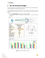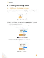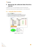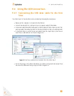
11.1. ALTUS NR2 RTK BASE-ROVER CELLULAR CONNECTION
Step 2: Configure output of differential corrections
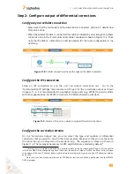
Configure your cellular connection
• Make sure that the cell modem of the Altus NR2 is connected. Section 5.2 details how
this can be done.
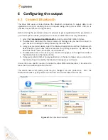
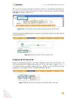
• When the cellular modem is connected this will be indicated by an active green cellular
connection line in the ‘Communication/Cellular’ window as shown in Figure 11-2. Take
note the IP address
1
indicated as it will be needed for the rover configuration in the
next step.
Figure 11-2:
Cellular connection active with assigned IP address indicated
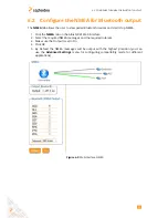
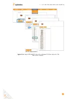
Configure the IPS connection
Setup an IPS connection so you the unit can stream corrections out.
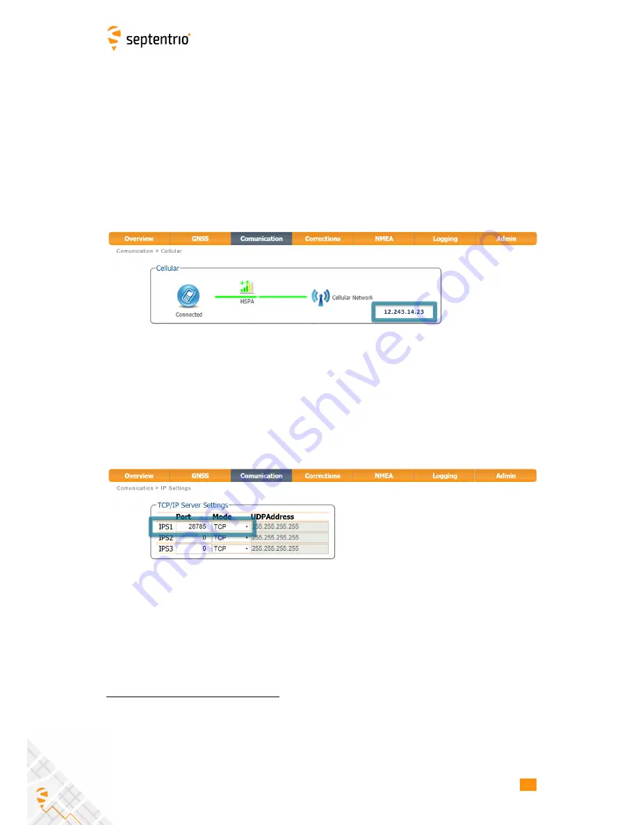
Go to the
‘Communication/IP Settings’ menu and set an IPS port for the corrections output as shown
in Figure 11-3. It is recommended to use higher range ports (e.g. 28785) to avoid conflicts
with other applications. For RTCM corrections, TCP Mode should be sufficient.
Figure 11-3:
Select an IPS ports on which to output differential corrections.
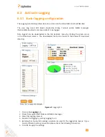
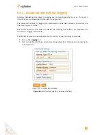
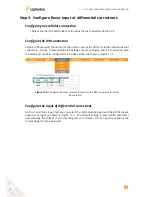
Configure the correction stream
On the ‘Corrections Output’ tab, you can select the type and number of differential
corrections that you want to send to the rover receiver. Make sure that you use the same
IPS connection you configured in the previous step. The sequence of steps are shown in
Figure 11-4. The messages necessary for RTK and DGNSS are selected by default
2
.
1
It is important to remember that with most mobile network providers the assigned IP address of the cellular
in the Altus NR2 will be changed every time that a new connection is made. As such the Rover units will need
to be aware of the new IP address (some mobile network providers allow you to use Fixed IP addresses with an
extra cost).
2
Note that if you do not have permissions for RTK Base corrections, you will only be allowed to output RTCM2
DGPS messages
44
Содержание Altus NR2
Страница 1: ...Altus NR2 User Manual ...
Страница 26: ...5 2 SET UP THE CELLULAR MODEM Figure 5 4 Cellular Status Connected 26 ...
Страница 72: ...14 1 CONFIGURATION Figure 14 2 Save to Boot pop up 72 ...
Страница 78: ...15 2 FRONT PANEL LEDS 15 2 Front Panel LEDs Figure 15 1 Front panel LED behaviour 78 ...

