68
Installation manual of system “bp408” - Electrical connection
7.7.4
Examples for a correct topology
7.7.4.1
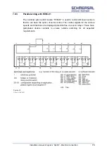
Individual control system
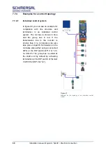
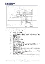
In figure 48, you can see an example for
compliance with line structure and
termination in an individual control
system. The car bus is shown in blue
and the group bus in red. If the
transmission line to the inverter is
shorter than 3 m, termination can also
take place in bp408. Termination on the
car takes place either using a connected
AWG or the DIP switch (DIP 2 at “on”)
on CLK-03. The group bus is ended at
the shaft end by default by activating
termination at the DIP switch of the last
CAP-01/02 (DIP 2 at “on”).
Figure 47:
Example for the topology of an individual control
system.
Содержание bp408
Страница 2: ......
Страница 24: ...24 Installation manual of system bp408 Safety instructions...
Страница 52: ...52 Installation manual of system bp408 The control system bp408...
Страница 58: ...58 Installation manual of system bp408 Installation and assembly...
Страница 80: ...80 Installation manual of system bp408 Electrical connection...
Страница 118: ...Installation manual of system bp408 Appendix 118 Appendix A Menu navigation bp408...
Страница 119: ...119 Installation manual of system bp408 Appendix B Update of the firmware via USB stick...

