94
Installation manual of system “bp408” - Commissioning
8.6
First drive with the return control
The return control is used to move the lift for assembly and maintenance purposes.
WARNING!
Follow the safety information in the chapter "Safety instructions".
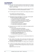
For your own safety, the return control, inspection and emergency stop buttons
and the Up and Down buttons must be wired into the safety circuit as specified in
the
circuit
diagram.
The bypass switch must be reset before normal operation is possible again. The
emergency stop contacts must not be bypassed.
If the return switch is on, terminals 11 and (102) must be de-energised and terminal
101 must be live.
If the correction switches S71 and S72 are present, they must be installed at the
end stop at the right deceleration point and must switch safely.
The contacts of the safety circuit must be closed Up or Down by pressing the return
drive key or must be bypassed through the return control On switch.
The drive commands are managed and controlled by the bp408 control system. If
there is an existing safety light barrier, terminal X7.53 (door B: X7.56) must carry
voltage. The command transmitter (return control) is located in the control cabinet,
in the control cabinet door or on the external control unit.
NOTE!
During the first drive with the return control, check whether the displayed speed
matches
the
speed
displayed
on
the
inverter
under
DIAGNOSE > SIGNALS > SHAFT SIGNALS
. If not, the conversion factors in both systems must be checked.
NOTE!
Turning on the inspection control will cancel the return control. In case of control
systems from Böhnke + Partner GmbH, the priority of the inspection control is given
even if movements of the lift car and the door drives are no longer possible with
the inspection control switched on and the return control activated. To counteract
the possible lock up of persons, an emergency call system according to EN 81-28
is required.
The return control essentially works like the inspection control. However, the
following safety devices are bypassed:
Speed limiter,
Buffer contacts,
Emergency limit switch,
Safety gear and
Low pressure switch on hydraulic lifts.
Содержание bp408
Страница 2: ......
Страница 24: ...24 Installation manual of system bp408 Safety instructions...
Страница 52: ...52 Installation manual of system bp408 The control system bp408...
Страница 58: ...58 Installation manual of system bp408 Installation and assembly...
Страница 80: ...80 Installation manual of system bp408 Electrical connection...
Страница 118: ...Installation manual of system bp408 Appendix 118 Appendix A Menu navigation bp408...
Страница 119: ...119 Installation manual of system bp408 Appendix B Update of the firmware via USB stick...


