100
Installation manual of system “bp408” - Commissioning
8.9
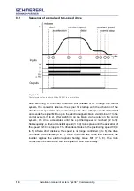
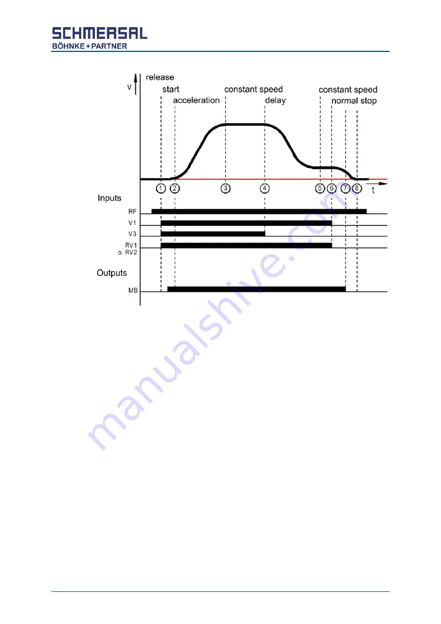
Sequence of a regulated two-speed drive
After switching on the main contactors and release of RF through the control
system, the convertor receives the signal for start-up with the activation of the
direction and speed V2. The inverter keeps the drive with speed n=0 at standstill
and sends the signal MB to open the electromagnetic brake via terminal 31 to the
control system (1 to 2). After switching on the brake via the relay on the control
system, the drive accelerates until the specified speed is reached (2 to 3).
Subsequently, a drive at constant speed (3 to 4) takes place until the activation of
the speed V2=0 is stopped. The drive decelerates to the positioning speed V0 (4
to 5). After a short distance, the speed is no longer controlled (5 to 6), the drive
continues to decelerate (6 to 7). When the drive has come to a standstill, the
inverter applies the electromagnetic holding brake MB (7 to 8). The main
contactors are switched off with the signal RF with a time delay.
Figure 59:
Control system of an inverter with the RVM-01 in a normal drive
Содержание bp408
Страница 2: ......
Страница 24: ...24 Installation manual of system bp408 Safety instructions...
Страница 52: ...52 Installation manual of system bp408 The control system bp408...
Страница 58: ...58 Installation manual of system bp408 Installation and assembly...
Страница 80: ...80 Installation manual of system bp408 Electrical connection...
Страница 118: ...Installation manual of system bp408 Appendix 118 Appendix A Menu navigation bp408...
Страница 119: ...119 Installation manual of system bp408 Appendix B Update of the firmware via USB stick...


