Installation manual of system “bp408” - Electrical connection
65
7.5
Safety circuit
NOTE!
The safety equipment prevent lift from starting when approaching it and cause an
immediate shutdown when travelling.
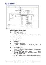
The safety circuit is designed, for example, for monitoring the following external
signals:
Closed position of maintenance and emergency doors,
Locking of car doors,
Locking of shaft doors,
Closed position of shaft doors,
Closed position of car doors,
Emergency stop car roof, car and control room,
Speed limiter,
Buffer contacts,
Emergency limit switch top and bottom,
Safety gear,
Door zone with safety circuit.
The doors and bolts are monitored for retracting with the doors open and for
levelling within the door zone. All travel and auxiliary contactors for the safety
circuit are designed in accordance with VDE 0660, device class D3. The signal
voltage for the safety circuit is max. 230 V AC.
The safety circuit works independently of the control system bp408. In the event
of a fault, the operating voltage of the output module for the control elements is
switched off.
Figure 42:
Standard switching of the safety circuit in the example of bp408
Содержание bp408
Страница 2: ......
Страница 24: ...24 Installation manual of system bp408 Safety instructions...
Страница 52: ...52 Installation manual of system bp408 The control system bp408...
Страница 58: ...58 Installation manual of system bp408 Installation and assembly...
Страница 80: ...80 Installation manual of system bp408 Electrical connection...
Страница 118: ...Installation manual of system bp408 Appendix 118 Appendix A Menu navigation bp408...
Страница 119: ...119 Installation manual of system bp408 Appendix B Update of the firmware via USB stick...

