76
Installation manual of system “bp408” - Electrical connection
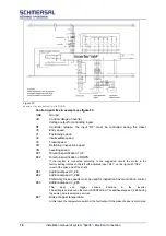
Control inputs like in example see figure 53:
GND
Ground
UO
Control voltage of inverter
Voltage output for controlling inputs
RF
Controller release, the input “RF” must be controlled during the travel.
V0
Entry speed
V1
Positioning speed
V2
Intermediate speed
V3
Travel speed
VR
Retaining / inspection speed
VN
Levelling speed
RV1
Direction specification 1 UP
RV2
Direction specification 2 DOWN
If the inverter is connected according to the suggested circuit, the motor in the
factory setting rotates on the left with activated input “RV1”, on the right with “RV2”
(view of the drive end of the shaft).
ZE1
Additional speed V_ZE
ZE2
Additional speed V_ZE2
Preferably, these speeds must be used for inspection travel and return control.
ZE3
Additional speed V_ZE3
This
input
can
trigger
various
functions
in
the
inverter.
The setting is carried out in the menu INTERFACES. The additional speed V_ZE3 having
the same name is selected ex works.
BCT
Brake chopper temperature.
At this input, the temperature switch or the fault output of the brake chopper is monitored
.
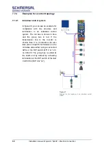
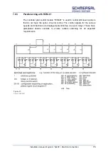
Figure 52:
Example of an inverter control with RVM-01.
Содержание bp408
Страница 2: ......
Страница 24: ...24 Installation manual of system bp408 Safety instructions...
Страница 52: ...52 Installation manual of system bp408 The control system bp408...
Страница 58: ...58 Installation manual of system bp408 Installation and assembly...
Страница 80: ...80 Installation manual of system bp408 Electrical connection...
Страница 118: ...Installation manual of system bp408 Appendix 118 Appendix A Menu navigation bp408...
Страница 119: ...119 Installation manual of system bp408 Appendix B Update of the firmware via USB stick...


