


Installation manual of system “bp408” - Troubleshooting
113
Contactor dropout (33)
The drive contactors are checked for dropout before the start.
Brake released (35)
The release of the brake shoes is checked by contacts before the start.
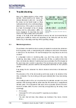
Door and bolt control
The closing of the safety circuit is monitored before the start. See menu
»Control times«.
Safety circuit
The input and output signal of the integrated safety circuit is monitored.
Regulations / LRV (34)
The fault output of the inverter is monitored.
Open/close brake (31)
The »mechanical brake« output of the inverter is monitored.
Impulses / level / correction (71-78)
The signals from the shaft are checked for plausibility if no AWG is used.
Re-levelling (without AWG: 73-74 / 77-78)
The monitoring takes place 20 times and 20 seconds per direction and floor.
Safety circuit (Terminals SSZ, 9, 10, 11, 12, 12A, 12B, 13, 14)
The monitoring is carried out during standstill and during the drive.
Correction signals /absolute encoder
The signals from the shaft are checked for plausibility.
Lock
Observations can be parameterised with a lock.
MONITORING NOTE!
Observations are directly displayed in the service menu under
DIAGNOSIS >
FAULTS
. They are registered and stored in the fault stack and in the fault list.
Содержание bp408
Страница 2: ......
Страница 24: ...24 Installation manual of system bp408 Safety instructions...
Страница 52: ...52 Installation manual of system bp408 The control system bp408...
Страница 58: ...58 Installation manual of system bp408 Installation and assembly...
Страница 80: ...80 Installation manual of system bp408 Electrical connection...
Страница 118: ...Installation manual of system bp408 Appendix 118 Appendix A Menu navigation bp408...
Страница 119: ...119 Installation manual of system bp408 Appendix B Update of the firmware via USB stick...